RV 45/55/65 Diagnostic Repair Manual RECREATIONAL VEHICLE GENERATOR ModelS 5 410, 5411, 5412, 5413, 5414 & 5415
SAFETY Throughout this publication, “DANGER!” and “CAUTION!” blocks are used to alert the mechanic to special instructions concerning a particular service or operation that might be hazardous if performed incorrectly or carelessly. PAY CLOSE ATTENTION TO THEM. DANGER! UNDER THIS HEADING WILL BE FOUND SPECIAL INSTRUCTIONS WHICH, IF NOT COMPLIED WITH, COULD RESULT IN PERSONAL INJURY OR DEATH.
Table of Contents Safety ............................ Inside Front Cover Section 1: Generator Fundamentals ....................... 3-7 Magnetism ................................................................. Electromagnetic Fields ..................................... Electromagnetic Induction .............................. A Simple AC Generator ......................................... A More Sophisticated AC Generator .............. Field Boost ..........................................................
Table of Contents Test 10 – Check Rotor Assembly................................................. 42 Test 11 – Check Main Circuit Breaker.......................................... 43 Test 12 – Check Load Voltage & Frequency................................. 43 Test 13 – Check Load Watts & Amperage.................................... 43 Test 14 – Try Cranking the Engine............................................... 44 Test 15 – Check Fuel Pump.........................................................
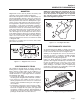
Section 1 GENERATOR FUNDAMENTALS Magnetism Magnetism can be used to produce electricity and electricity can be used to produce magnetism. Much about magnetism cannot be explained by our present knowledge. However, there are certain patterns of behavior that are known. Application of these behavior patterns has led to the development of generators, motors and numerous other devices that utilize magnetism to produce and use electrical energy. See Figure 1-1.
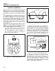
Section 1 GENERATOR FUNDAMENTALS A Simple AC Generator Figure 1-4 shows a very simple AC Generator. The generator consists of a rotating magnetic field called a ROTOR and a stationary coil of wire called a STATOR. The ROTOR is a permanent magnet which consists of a SOUTH magnetic pole and a NORTH magnetic pole. As the ROTOR turns, its magnetic field cuts across the stationary STATOR. A voltage is induced Into the STATOR windings.
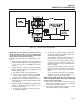
Section 1 GENERATOR FUNDAMENTALS Figure 1-7. – Generator Operating Diagram NOTE: AC output frequency at 3720 rpm will be about 60 Hertz. The “No-Load” is set slightly high to prevent excessive rpm, frequency and voltage droop under heavy electrical loading. Generator operation may be described briefly as follows: 1. Some “residual” magnetism is normally present in the Rotor and is sufficient to induce approximately 7 to 12 volts AC Into the STATOR’s AC power windings. 2.
Section 1 GENERATOR FUNDAMENTALS Field Boost When the engine is cranked during startup, the starter contactor is energized closed. Battery voltage is then delivered to the starter motor and the engine cranks. During cranking, battery voltage flows through a resistor and a field boost diode in the Printed Circuit Board, then to the Rotor via brushes and slip rings. This is called “Field Boost” voltage. Field boost voltage is delivered to the Rotor only while the engine is cranking.
Section 1 GENERATOR FUNDAMENTALS CB1 T1 RED T2 WHITE CB2 Figure 1-8. – Connection for 120 Volts Only STATOR WINDINGS Reconnection for Dual Voltage Output: When connected for dual voltage output, Stator output leads 11 and 44 form two “hot” leads (T1 – Red, and T3 – Black). The junction of leads 22 and 33 form the “Neutral” line (T2 – White). For dual voltage output, the “Neutral” line remains grounded.
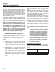
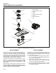
Section 2 Major Generator Components 8 1 1. BRUSH HOLDER 2. UPPER BEARING CARRIER 3. STATOR 4. ROTOR 2 5. LOWER BEARING CARRIER 6. ENGINE 7. PULLEYS AND BELT 3 8. FANS 6 4 5 8 7 Figure 2-1. Exploded View of Generator Rotor Assembly Stator Assembly The Rotor is sometimes called the “revolving field”, since it provides the magnetic field that induces a voltage into the stationary Stator windings.
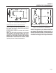
Section 2 MAJOR GENERATOR COMPONENTS 2 11S 11S 11S 22S 22S 22S 4 4 0 0 6 6 2 2 6 0 11 22 + - VOLTAGE REGULATOR 33 Stator 6 2 4 0 44 11S 22S Leads 2 & 6 = Stator Excitation Winding Leads 11S & 22S = Voltage Sensing Leads Leads 11 & 22, 33 & 44 = AC Power Windings Figure 2-2. – Stator Output Leads Brush Holder The brush holder is retained in the rear bearing carrier by two M5 screws.
Section 2 Major Generator Components NOTE: If, for any reason, sensing voltage to the regulator is lost, the regulator will shut down and excitation output to the Rotor will be lost. The AC output voltage will then drop to a value that is commensurate with Rotor residual magnetism (about 7-12 VAC). Without this automatic shutdown feature, loss of sensing (actual) voltage to the regulator would result in a “full field” or “full excitation” condition and an extremely high AC output voltage.
Section 2 Major Generator Components Control Panel Component Identification STARTER CONTACTOR RELAY (SCR) TERMINAL BLOCK (TB) “4-TAB CONNECTOR” CONTROL BOARD (PCB) WITH J1 CONNECTOR GOVERNOR ACTUATOR J2 CONNECTOR VOLTAGE REGULATOR (VR) WITH RED LED START/STOP SWITCH (SW1) WITH RED LED 7.5 AMP DC FUSE (F1) CIRCUIT BREAKERS (CB1 & CB2) ENGINE CONNECTOR (C1) 6 WIRE GROUND TERMINAL REAR VIEW Figure 2-9.
Section 3 Insulation Resistance Tests Effects of Dirt and Moisture Moisture and dirt are detrimental to the continued good operation of any generator set. If moisture is allowed to remain in contact with the Stator and Rotor windings, some of the moisture will be retained in voids and cracks of the winding insulation. This will result in a reduced Insulation resistance and, eventually, the unit’s AC output will be affected. Insulation used in the generator is moisture resistant.
Section 3 Insulation Resistance Tests vents that will not attack such materials. Use a soft brush or cloth to apply the solvent. Be careful to avoid damage to wire or winding insulation. After cleaning, dry all components thoroughly using moisture-free, low-pressure compressed air. DANGER!: DO NOT ATTEMPT TO WORK WITH SOLVENTS IN ANY ENCLOSED AREA. PROVIDE ADEQUATE VENTILATION WHEN WORKING WITH SOLVENTS. WITHOUT ADEQUATE VENTILATION, FIRE, EXPLOSION OR HEALTH HAZARDS MAY EXIST . WEAR EYE PROTECTION.
Section 3 Insulation Resistance Tests 3. Apply 1000 volts. DO NOT APPLY VOLTAGE LONGER THAN 1 SECOND. 2 6 11 22 The Megohmmeter 33 Stator If an insulation breakdown is indicated, clean and dry the Rotor then repeat the test. Replace the Rotor if it fails the second test (after cleaning and drying). 44 11S 22S Leads 2 & 6 = Stator Excitation Winding Leads 11S & 22S = Voltage Sensing Leads Leads 11 & 22, 33 & 44 = AC Power Windings Figure 3-2.
Section 4 MEASURING ELECTRICITY Meters Measuring AC Voltage Devices used to measure electrical properties are called meters. Meters are available that allow one to measure (a) AC voltage, (b) DC voltage, (c) AC frequency, and (d) resistance in ohms. The following apply: ❏ To measure AC voltage, use an AC voltmeter. ❏ To measure DC voltage, use a DC voltmeter. ❏ Use a frequency meter to measure AC frequency In “Hertz” or “cycles per second”.. ❏ Use an ohmmeter to read circuit resistance, in “ohms”.
Section 4 MEASURING ELECTRICITY Correct engine and Rotor speed is maintained by a stepper motor governor. For models rated 60 Hertz, the governor is generally set to maintain a no-load frequency of about 60 Hertz with a corresponding output voltage of about 124 volts AC line-to-neutral. Measuring Current To read the current flow, in AMPERES, a clamp-on ammeter may be used. This type of meter indicates current flow through a conductor by measuring the strength of the magnetic field around that conductor.
Section 4 MEASURING ELECTRICITY Electrical Units AMPERE: The rate of electron flow in a circuit is represented by the AMPERE. The ampere is the number of electrons flowing past a given point at a given time. One AMPERE is equal to just slightly more than six thousand million billion electrons per second. With alternating current (AC), the electrons flow first in one direction, then reverse and move in the opposite direction. They will repeat this cycle at regular intervals.
Section 5 ENGINE DC CONTROL SYSTEM Introduction CIRCUIT CONDITION – Rest: Battery voltage is available to the Printed Circuit Board (PCB) from the vehicle BATTERY via the positive (RED) battery cable to the isolated positive (RED) terminal stud, located in the control panel. The power is supplied to Wire 13, a 7.5 amp FUSE (F1), the STARTER CONTACTOR RELAY (SCR) and Wire 15/Pin 4 on the PCB. However, PCB action is holding the circuits open, and no action can occur.
Section 5 ENGINE DC CONTROL SYSTEM CIRCUIT CONDITION – CRANKING: When the STARTER CONTACTOR RELAY (SCR) closes, battery voltage is also delivered to PCB Pin 13 . This voltage is reduced for use as field boost and is output from PCB Pin 13 to the rotor. While cranking, the CHOKE SOLENOID (CS) is energized by grounding Wire 90 cyclically by PCB action (two seconds on, two seconds off). Also while cranking, PCB action energizes Pin 5, and delivers battery voltage to the Wire 14 circuit.
Section 5 ENGINE DC CONTROL SYSTEM CIRCUIT CONDITION – RUNNING: Printed Circuit Board action terminates DC output to the STARTER CONTACTOR RELAY (SCR), which then de-energizes to end cranking. PCB action terminates DC output to the CHOKE SOLENOID (CS). With the FUEL PUMP (FP) and FUEL SOLENOID (FS) operating and ignition occurring, the engine should start, and the STARTSTOP SWITCH (SW1) is released. This voltage is delivered to the PCB via Wire 18A to prevent STARTER MOTOR engagement above a certain rpm.
Section 5 ENGINE DC CONTROL SYSTEM CIRCUIT CONDITION – SHUTDOWN: Should engine oil temperature exceed a preset value, the switch contacts will close. Wire 85 from the Printed Circuit Board will connect to frame ground. PCB action will then initiate a shutdown and will cause the red led light on SW1 to flash 6 times then repeat. Setting the START-STOP SWITCH (SW1) or the REMOTE PANEL START-STOP SWITCH to its “STOP” position connects the Wire 18 circuit to frame ground.
Section 5 ENGINE DC CONTROL SYSTEM Printed Circuit Board DIP SWITCH J1 CONNECTOR GENERAL: The Printed Circuit Board (PCB) mounted inside the generator control panel is responsible for cranking, startup, running and shutdown operations. The board interconnects with other components of the DC control system to turn them on and off at the proper times. It is powered by fused 12 VDC power from the unit battery.
Section 5 ENGINE DC CONTROL SYSTEM cold weather starting, voltage drop between the battery and starter should not exceed 0.12 volt per 100 amperes of cranking current. Select the battery cables based on total cable length and prevailing ambient temperature. Generally, the longer the cable and the colder the weather, the larger the required cable diameter. The following chart applies: CABLE LENGTH (IN FEET) RECOMMENDED CABLE SIZE 0-10 No. 2 11-15 No. 0 16-20 No.
Section 5 ENGINE DC CONTROL SYSTEM a. With Wire 17 grounded, a Crank Relay on the circuit board energizes and battery voltage is delivered to the Starter Contactor Relay via Wire 56. The Starter Contactor Relay energizes, its contacts close and the Starter Contactor is energized via wire 16. Its contacts close and the engine cranks. b. With Wire 17 grounded, a Run Relay on the circuit board energizes and battery voltage is delivered to the Wire 14 circuit.
Section 6 TROUBLESHOOTING FLOWCHARTS Introduction The “Flow Charts” in this section may be used in conjunction with the “Diagnostic Tests” of Section 7. Numbered tests in the Flow Charts correspond to identically numbered tests of Section 7. Problems 1 through 4 apply to the AC generator only. Beginning with Problem 5, the engine DC control system is dealt with.
Section 6 TROUBLESHOOTING FLOWCHARTS Problem 2 – Generator Produces Zero Voltage or Residual Voltage (5-12VAC) TEST 11 – CHECK MAIN CIRCUIT BREAKER GOOD RESET TO “ON” OR REPLACE IF BAD A TEST 4 – PERFORM FIXED EXCITATION TEST / ROTOR AMP DRAW B D C TEST 8 – CHECK BRUSH LEADS BAD GOOD TEST 6 – TEST STATOR DPE WINDING TEST 5 – CHECK FIELD BOOST REPAIR OR REPLACE GOOD BAD GOOD BAD REPAIR OR REPLACE THEN RE-TEST INSULATION RESISTANCE TEST, PAGE 13 BAD REPLACE VOLTAGE REGULATOR REPAIR OR REP
Section 6 TROUBLESHOOTING FLOWCHARTS Problem 2 – Generator Produces Zero Voltage or ResidualVoltage (5-12VAC) (continued) E TEST 4 – PERFORM FIXED EXCITATION TEST / ROTOR AMP DRAW CHECK VOM FUSES – VERIFY AMP METER FUNCTIONS G F TEST 10 – CHECK ROTOR ASSEMBLY REPLACE FUSES – THEN RE-TEST (PERFORM BOTH TEST 7 & 8) BAD TEST 6 – TEST STATOR DPE WINDING REPAIR OR REPLACE TEST ROTOR INSULATION, PAGE 14 GOOD TEST 7 – CHECK SENSING LEADS / POWER WINDINGS REPAIR OR REPLACE EITHER OR BOTH BAD GOOD INSU
Section 6 TROUBLESHOOTING FLOWCHARTS Problem 4 – Engine Overspeed Warning Code Flashing on SW1 LEd (4 Flashes) TEST 2 – CHECk STEPPER MOTOR CONTROL GOOD CHECk WIRE 18A GOOD TEST 31 – CHECk & ADjUST IGNITION MAGNETOS BAD BAD BAD REPLACE STEPPER MOTOR REPAIR OR REPLACE ADjUST, REPAIR OR REPLACE GOOD REPLACE PRINTED CIRCUIT BOARD Proble 5 – Priming Function Does Not Work (Gasoline Models) TEST 14 – TRY CRANKING THE ENGINE WON’T CRANK ENGINE CRANKS NORMALLY STILL WON’T PRIME TEST 20 – CHECK STA
Section 6 TROUBLESHOOTING FLOWCHARTS Problem 6 - Engine Will Not Crank TEST 16 – CHECk 7.5 AMP FUSE TEST 17 – CHECk BATTERY & CABLES (CHECk SW1 LED FOR LOW BATTERY WARNING – 2 FLASHES) GOOD FUSE BAD RECHARGE OR REPLACE BATTERY – CLEAN, REPAIR OR REPLACE BAD CABLE(S) BAD REPLACE FUSE FUSE BLOWS GO TO PROBLEM 10 GOOD TEST 18 – CHECk POWER SUPPLY TO PRINTED CIRCUIT BOARD GOOD TEST 20 – CHECk START-STOP SWITCH BAD BAD CHECk WIRING AND WIRE CONNECTIONS.
Section 6 TROUBLESHOOTING FLOWCHARTS Problem 7 – Engine Cranks But Will Not Start (Gasoline Units) (Overcrank Warning Code on SW1 LED – 3 Flashes) TEST 25 – CHECK FUEL SUPPLY TEST 26 – CHECK WIRE 14 POWER SUPPLY O.K.
Section 6 TROUBLESHOOTING FLOWCHARTS Problem 7 – Engine Cranks But Will Not Start (LP Units) (Overcrank Warning Code on SW1 LED – 3 Flashes) TEST 25 – CHECK FUEL SUPPLY O.K.
Section 6 TROUBLESHOOTING FLOWCHARTS Problem 8 – Engine Starts Hard and Runs Rough (Gasoline Units) TEST 25 – CHECK FUEL SUPPLY TEST 29 – CHECK IGNITION SPARK GOOD TEST 30 – CHECK SPARK PLUGS GOOD GOOD BAD LOW FUEL ENGINE MISS IS APPARENT CLEAN AND REGAP OR REPLACE SPARK PLUG REPLENISH FUEL SUPPLY TEST 33 – CHECK CARBURETION TEST 31 – CHECK AND ADJUST IGNITION MAGNETOS GOOD BAD REPLACE MAGNETOS TEST 34 – CHECK CHOKE SOLENOID GOOD ENGINE RUNS O.K.
Section 6 TROUBLESHOOTING FLOWCHARTS Problem 8 – Engine Starts Hard and Runs Rough (LP Units) TEST 25 – CHECK FUEL SUPPLY TEST 29 – CHECK IGNITION SPARK GOOD TEST 30 – CHECK SPARK PLUGS GOOD GOOD BAD LOW FUEL ENGINE MISS IS APPARENT CLEAN AND REGAP OR REPLACE SPARK PLUG REPLENISH FUEL SUPPLY TEST 32 – CHECK VALVE ADJUSTMENT TEST 31 – CHECK AND ADJUST IGNITION MAGNETOS GOOD BAD CHECK FLYWHEEL KEY – SEE TEST 31 ON PAGE 57 REPLACE MAGNETOS GOOD BAD ADJUST VALVES TEST 35 – CHECK ENGINE / CYL
Section 6 TROUBLESHOOTING FLOWCHARTS Problem 9 – High Oil Temperature Fault (6 Flashes) or Low Oil Pressure Fault (5 Flashes) LOW OIL PRESSURE – 5 FLASHES ON SW1 LED TEST 25 – CHECK FUEL SUPPLY CHECK ENGINE OIL LEVEL GOOD NO FUEL OIL LEVEL LOW GOOD REPLENISH FUEL TEST 36 – CHECK OIL PRESSURE SWITCH GOOD REPLENISH OIL TEST 37 – CHECK WIRE 86 FOR CONTINUITY BAD BAD REPAIR OR REPLACE REPLACE SWITCH HIGH OIL TEMPERATURE – 6 FLASHES ON SW1 LED CHECK ENGINE OIL LEVEL OIL LEVEL O.K.
Section 6 TROUBLESHOOTING FLOWCHARTS Problem 10 – 7.5A (F1) Fuse Blowing INSTALL NEW 7.5 AMP FUSE CHECK THAT FUSE HOLDER IS NOT GROUNDED FUSE BLOWS UPON INSTALLATION FAIL REMOVE WIRE 15 FROM JI HARNESS CONNECTOR. DOES FUSE BLOW? (SEE NOTE A) REPLACE PRINTED CIRCUIT BOARD NO YES CHECK WIRE 15 FOR SHORT TO GROUND FUSE IS GOOD BUT BLOWS WHEN STARTSTOP SWITCH IS PRESSED DISCONNECT JI HARNESS FROM ENGINE CONTROLLER CIRCUIT BOARD AND CHECK WIRE 14 FOR SHORT TO GROUND.
Section 7 DIAGNOSTIC TESTS Introduction The “Diagnostic Tests” in this chapter may be performed in conjunction with the “Flow Charts” of Section 6. Test numbers in this chapter correspond to the numbered tests in the “Flow Charts”. Tests 1 through 13 are procedures involving problems with the generator’s AC output voltage and frequency (Problems 1 through 3 in the “Flow Charts”).
Section 7 DIAGNOSTIC TESTS 4. If no movement is seen in Step 3 remove the control panel cover. Verify the six pin connector (J2) on the Printed Circuit Board is seated properly, remove the connector and then replace it and test again. Verify the dip switches are correctly set. NOTE: The dip switches on the Printed Circuit Board are factory set in the “OFF” or DOWN position. Refer to Figure 5.2 on Page 22. 5. If problem continues remove six pin connector (J2) from Printed Circuit Board.
Section 7 DIAGNOSTIC TESTS TEST 4 RESULTS A B C D E F G VOLTAGE RESULTS WIRE 2 & 6 EXCITATION WINDING ABOVE 60 VAC ABOVE 60 VAC BELOW 60 VAC ZERO OR RESIDUAL VOLTAGE (5-12 VAC) BELOW BELOW 60 VAC ABOVE 60 VAC VOLTAGE RESULTS WIRE 11S & 22S POWER WINDING SENSE LEADS ABOVE 60 VAC BELOW 60 VAC ABOVE 60 VAC ZERO OR RESIDUAL VOLTAGE (5-12 VAC) BELOW BELOW 60 VAC ABOVE 60 VAC ROTOR AMP DRAW RV45 (MODEL 5410/5411) 1.1 A ± 20% 1.1 A ± 20% 1.1 A ± 20% ZERO CURRENT DRAW 1.4 A .
Section 7 DIAGNOSTIC TESTS 1.11 Amp VOLTAGE REGULATOR PROCEDURE: 1. Set VOM to measure DC voltage. 2 BLACK TEST LEAD 6 2. Disconnect Wire 4 from the Voltage Regulator and connect the positive (+) test lead to it. Connect the negative (-) test lead to a clean frame ground. 0 13 13 15 RED TEST LEAD 22S 11S FUSE HOLDER (F1) 4 4 Loss of the field boost function may or may not result in a problem with AC output voltage.
Section 7 DIAGNOSTIC TESTS c. Connect one VOM test lead to Stator lead 2 the other test lead to Stator lead 33. “Infinity” should be indicated. RESULTS: 1. If the Stator excitation (DPE) windings are open or shorted, replace the Stator assembly. 2 6 A. Schematic 2 6 B. Pictorial Figure 7-8. – Stator Excitation Winding PROCEDURE: 1. Disconnect Wire 2 from the Voltage Regulator. 2. Disconnect Wire 6 from the Voltage Regulator. 3. Set a VOM to its “Rx1” scale and zero the meter. 4.
Section 7 DIAGNOSTIC TESTS AC POWER WINDING RESISTANCE * RV45 (Model 5410/5411) ACROSS WIRES: OHMS 11 & 22 0.396Ω 11S & 22S 0.396Ω 33 & 44 0.396Ω CB1 CB2 AC POWER WINDING RESISTANCE * RV55 (Model 5412/5413) ACROSS WIRES: OHMS 11 & 22 0.28Ω − 0.32Ω 11S & 22S 0.28Ω − 0.32Ω 33 & 44 0.28Ω − 0.32Ω AC POWER WINDING RESISTANCE * RV65 (Model 5414/5415) ACROSS WIRES: OHMS 11 & 22 0.209Ω − 0.242Ω 11S & 22S 0.209Ω − 0.242Ω 33 & 44 0.209Ω − 0.242Ω * Resistance values In ohms at 20° C. (68° F.).
Section 7 DIAGNOSTIC TESTS 4 0 RESULTS: 1. Replace bad brushes. Clean slip rings, if necessary. 2. If brushes and rings are good, go to Test 10. Test 10 – Check Rotor Assembly DISCUSSION: During the “Test 4 – Fixed Excitation Test,” if AC output voltage did not come up to about one-half rated volts, one possible cause might be a defective Rotor. The Rotor can be tested for an open or shorted condition using a volt-ohm-milliammeter (VOM). Also see Chapter Three, “INSULATION RESISTANCE TESTS”.
Section 7 DIAGNOSTIC TESTS 2. If breaker is “OFF”, reset to the “ON” position and check for AC output. 3. If breaker is “ON” and “Continuity” is not measured, replace the defective circuit breaker. Test 12 – Check Load Voltage & Frequency DISCUSSION: If engine speed appears to drop off excessively when electrical loads are applied to the generator, the load voltage and frequency should be checked. POSITIVE (+) TEST LEAD Figure 7-11.
Section 7 DIAGNOSTIC TESTS Test 14 – Try Cranking the Engine DISCUSSION: If the Start-Stop Switch on the generator panel is actuated, but the Fuel Pump does not run (priming function doesn’t work), perhaps battery voltage is not available. Short to Ground: 6. To test for a shorted fuel pump coil, connect one test lead to the Red Wire (Pin 2 of Connector 2, see Figure 7-14). Connect the other test lead to the fuel pump housing. “Infinity” should be measured.
Section 7 DIAGNOSTIC TESTS Test 16 – Check 7.5 Amp Fuse 2. Recharge the battery, if necessary. 3. Replace the battery, if necessary. DISCUSSION: If the panel-mounted 7.5 amp fuse (F1) has blown, engine cranking will not be possible. 4. If battery is good, but engine will not crank, go to Test 18. Test 18 – Check Power Supply to Printed Circuit Board Figure 7-15. – 7.5 Amp Fuse PROCEDURE: Push In on fuse holder cap and turn counterclockwise. Then, remove the cap with fuse. Inspect the Fuse.
Section 7 DIAGNOSTIC TESTS Test 19 – Check Continuity of Wire 17 712 DISCUSSION: A faulty condition in Wire 17 could prevent the unit from cranking when the Start-Stop switch is held in the “Start” position. PROCEDURE: 1. Disconnect Wire 17 from its Switch terminal and connect it to frame ground. The engine should crank. If unit cranks, proceed to Step 2. If unit does not crank when grounding Wire 17, go back to Test 18 “Check Power Supply to Printed Circuit Board”, then repeat Step 1.
Section 7 DIAGNOSTIC TESTS 5. Connect the VOM positive (+) test lead to Wire 56 (Pin Location J1-9) at the Printed Circuit Board. Connect the other test lead to frame ground. 0000 8 7 1 4 2 5 3 6 RESULTS: 1. If battery voltage was measured in Step 6, but not in Step 4, repair or replace Wire 56 between the Printed Circuit Board and Starter Contactor Relay. DEPRESSED AWAY FROM TERMINAL BEING TESTED 2. If battery voltage was not available in Step 6, replace the Printed Circuit Board.
Section 7 DIAGNOSTIC TESTS “Infinity” should be measured. Set the Start-Stop Switch to “START”. The meter should now read “Continuity”. Short to Ground: 3. Set the VOM to measure resistance (“R x 1” scale). Disconnect Wire 56 from the Starter Contactor Relay (SCR). Connect one meter test lead to the SCR terminal from which Wire 56 was just removed. Connect the other meter test lead to a clean frame ground. Starter Contactor Relay coil resistance of 155 ohms should be measured.
Section 7 DIAGNOSTIC TESTS be indicated by excessive current draw or no RPM. 3. A defective Starter Motor switch. 4. Broken, damaged or weak magnets. 5. Starter drive dirty or binding. DISCUSSION: Test 21 verified that Printed Circuit Board action is delivering DC voltage to the Starter Contactor Relay (SCR). Test 22 verified the operation of the SCR. Test 23 verified the operation of the Starter Contactor (SC). Another possible cause of an “engine won’t crank” problem is a failure of the Starter Motor.
Section 7 DIAGNOSTIC TESTS Remove Starter Motor: It is recommended that the Starter Motor be removed from the engine when testing Starter Motor performance. Assemble starter to test bracket and clamp test bracket in vise (Figure 7-26). Testing Starter Motor: 1. A fully charged 12 volt battery is required. 2. Connect jumper cables and clamp-on ammeter as shown in Figure 7-26. 3.
Section 7 DIAGNOSTIC TESTS Test 25 – Check Fuel Supply DISCUSSION (Gasoline Models): If the engine cranks but won’t start, don’t overlook the obvious. The fuel supply may be low. Many RV generator installations “share” the fuel tank with the vehicle engine. When such is the case, the Installer may have used a generator fuel pickup tube that is shorter than the vehicle engine’s pickup tube. Thus, the generator will run out of gas before the vehicle engine. PROCEDURE: Check fuel level in the supply tank.
Section 7 DIAGNOSTIC TESTS The greater the airflow through the carburetor venturi, the lower the pressure at the venturi throat. The lower the pressure at the venturi throat, the greater the diaphragm movement, and the greater the movement of the regulator valve. The more the regulator valve opens, the greater the gas flow that is proportional to airflow through the generator.
Section 7 DIAGNOSTIC TESTS Test 27 – Check Wire 18 DISCUSSION: Wire 18 controls sending the STOP signal to the Printed Circuit Board. Coach manufacturers sometimes install a 15 to 30 foot remote harness. If unit shuts down or will not start, a possible ground exists on Wire 18. PROCEDURE: 1. Disconnect the customer installed remote harness connector from the generator. Then press the generator Start-Stop switch to the “Start” position.
Section 7 DIAGNOSTIC TESTS 3. If “Continuity” is not measured in Step 5, repair or replace Wire 0 between the Fuel Solenoid and ground terminal. 4. If “Continuity” is not measured in Step 6, repair or replace Carburetor ground wire. 5. If the Fuel Solenoid operates, proceed to Test 29. Test 29 – Check Ignition Spark 6. If spark jumps the tester gap intermittently, the problem may be in the Ignition Magneto. Proceed to Test 31.
Section 7 DIAGNOSTIC TESTS 2. If spark plugs are good for gasoline models, go to Test 33. For LPG models, go to Test 32. Test 31 – Check and Adjust Ignition Magnetos Figure 7-34. – Cylinder Balance Test The cylinder balance test will also detect a cylinder that is not functioning. When grounding out one cylinder there will be no RPM loss. When the other cylinder is grounded out the engine will stop.
Section 7 DIAGNOSTIC TESTS to Step 2. If the unit does not produce spark or has weak spark go to Step 4. 2. Do the following: a. Set a VOM to measure resistance. Connect the positive (+) meter test lead to Wire 18A (Wire 18A still removed from the J1 connector) Connect the negative (-) meter test lead to a clean frame ground. “Infinity” should be measured, or 0.5 to 1M ohms, depending upon the type of VOM used. If “Continuity” is measured proceed to Step 12. b. Set a VOM to the diode test range.
Section 7 DIAGNOSTIC TESTS 3. If “Infinity” was not measured in Step 15, repair or replace grounded Wire 18A between the J1 Connector and the insulated terminal stud or defective insulated terminal stud. 1. Loosen the rocker arm jam nut. Use a 10mm allen wrench to turn the pivot ball stud while checking the clearance between the rocker arm and valve stem with a feeler gauge (see Figure 7-39). 4.
Section 7 DIAGNOSTIC TESTS Test 33 – Check Carburetion Test 34 – Check Choke Solenoid DISCUSSION: If the engine cranks but will not start, one possible cause of the problem might be the carburetion system. DISCUSSION: The automatic choke is active only during cranking. When the Start-Stop Switch is held at “START”, a crank relay on the Printed Circuit Board is energized closed to (a) crank the engine and (b) deliver a cyclic voltage to the Choke Solenoid via Wire 14.
Section 7 DIAGNOSTIC TESTS in its coil, tighten the two screws. Verify that the choke solenoid plunger and linkage move freely without any drag or resistance that may restrict movement. CHOKE CONTROL ROD PLUNGER 6. Set the VOM to measure resistance. Disconnect Connector 3 from the Choke Solenoid. Connect one test lead to Wire 0 (Pin 1) of Connector 3, going to the control panel. Connect the other test lead to frame ground. “Continuity” should be measured. 7. Set the VOM to measure resistance.
Section 7 DIAGNOSTIC TESTS Discussion: The Cylinder Leak Down Tester checks the sealing (compression) ability of the engine by measuring air leakage from the combustion chamber. Compression loss can present many different symptoms. This test is designed to detect the section of the engine where the fault lies before disassembling the engine. PROCEDURE: 1. Remove both spark plugs. Procedure: 1. Remove a spark plug. 5. Repeat the procedure for the remaining cylinder and record the highest reading. 2.
Section 7 DIAGNOSTIC TESTS 2. Locate Pin Location J1-6 on the harness end of the J1 Connector. 3. Remove Wire 86 from the Low Oil Pressure switch (LOP). 4. Set a VOM to its “Rx1” scale and zero the meter. 5. Insert one meter test lead into the end of Wire 86 disconnected from the LOP. Insert the other meter test lead into Pin Location J1-6 on the harness end of the J1 Connector. RESULTS: 1. If “Continuity” is not indicated, repair or replace Wire 86. 2.
Section 7 DIAGNOSTIC TESTS 3. Connect the test leads of a VOM across the switch terminals. The meter should read “Infinity”. 4. Heat the oil. When oil temperature reaches approximately 270-284° F., the switch contacts should close and the meter should read “Continuity”. RESULTS: 1. If “Continuity” is not indicated, repair or replace Wire 85. 2. If “Continuity” is indicated, replace the Printed Circuit Board.
Section 7 DIAGNOSTIC TESTS Results: 1. If Choke Plate is binding in Step 1, repair or replace binding Choke Plate. If Bi-Metal Heater Assembly tests good, go to Test 32. 2. If continuity was not measured in Step 3, repair or replace Wire 14 between the 4-tab Connector and Connector 3. 3. If the resistance value is incorrect in the Short to Ground step, or the Bi-Metal Heater Assembly does not function with voltage present, replace the Bi-Metal Heater Assembly. RESULTS: 1.
Section 9 Exploded Views Base & Pulley – Drawing No.
Section 9 Exploded Views ITEM QTY. 1 1 2 DESCRIPTION ITEM QTY. DESCRIPTION TRAY, 530 RV 24 1 FRAME GT530 RV MOUNTING 2 NUT FLANGE 5/16-18 LOCK 25 1 SPACER, SAFETY BOLT .375 I.D. 3 8 NUT HEX 5/16-18 STEEL 26 2 SCREW HHC 5/16-18 X 3 SPC 4 12 WASHER LOCK M8-5/16 27 1.5ft TAPE ELEC UL FOAM 1/8 X 1/2 5 13 WASHER FLAT 5/16-M8 ZINC 28 1 DUCT AIR OUT 6 2 SCREW HHC 3/8-24 X 1-1/2 G8 29 1 GASKET, AIR OUT DUCT 7 1 BELT V-RIBBED 4L X 43.
Section 9 Exploded Views Enclosure – Drawing No.
Section 9 Exploded Views ITEM QTY. DESCRIPTION ITEM QTY. 1 1 2 2 3 1 FOAM ENCLOSURE DOOR 4 23 DESCRIPTION ENCLOSURE DOOR 22* 1 BRACKET, 530 RV REGULATOR (LP) SLIDE LATCH, FLUSH 23 1 FOAM BACK ENCLOSURE ALT SIDE * 1 FOAM BACK ENCLOSURE ALT SIDE (LP) NUT FLANGE M6-1.0 NYLOK 24 1 ENCLOSURE ROOF * 26 NUT FLANGE M6-1.
Page 68 14 15 12 13 17 6 16 52 28 27 25 26 24 25 24 11 18 10 9 20 21 55 23 22 20 20 21 51 8 TO "A" 19 1 3 2 53 30 REAR VIEW OG3530 TO AIRBOX 54 29 38 4 7 35 37 36 36 6 33,34 47 40 39 41 31 48 17 42 43 44 5 32 "A" 12 46 49 45 45 50 Section 9 Exploded Views Control Panel – Drawing No.
Section 9 Exploded Views ITEM QTY. ITEM QTY. 1 1 DESCRIPTION SCREW HHC M6-1.0 X 25 G8.8 32 4 DESCRIPTION SCREW PPHM #6-32 X 1/4 SEMS 2 2 SCREW PLASTITE HI-LOW #10X3/8 33 1 FUSE 7.5AXBK/AGC7.5NX 3 1 BUSHING SNAP SB-1093-937 34 1 HOLDER FUSE 4 1 WIRE HARNESS C/PNL FRAME 35 1 SWITCH RKRSPDT(ON)OFF(ON)ILLUM 5 1 NUT HEX M6 X 1.0 G8 YEL CHR 36 4 NUT HEX LOCK M5-0.
Section 9 Exploded Views Engine Accessories – Drawing No.
Section 9 Exploded Views ITEM QTY. ITEM QTY. 1 1 DESCRIPTION FRAME 49 1 DESCRIPTION ASSY, OIL DRAIN FITTING 3 1 ENGINE WRAPPER, STARTER SIDE 50 1 OIL FILTER SUPPORT 4 8 SCREW HHFC M8-1.25 X 14 51 2 SCREW SWAGE 1/4-20 X 1 5 1 SNAP BUSHING 52 1 OIL FILTER 6 14 SCREW CRIMPTITE 10-24 X 1/2 53 1 OIL PRESSURE SWITCH 5 PSI 7 1 SHIELD WRAPPER, CYLINDER #1 54 1 SWITCH, THERMAL 270F 8 13 SCREW HHFC M6-1.0 X 12 G8.
Section 9 Exploded Views 530 RV Engine – Drawing No.
Section 9 Exploded Views ITEM QTY. DESCRIPTION ITEM QTY. DESCRIPTION 1 2 SEAL D 35 X 48.2 29 4 VALVE SPRING 2 1 3/8” SQUARE HEAD PLUG 30 4 VALVE RETAINER 3 9 SCREW HHFC M8 – 1.25 X 45 31 8 KEEPER, VALVE SPRING 4 1 GEAR COVER 32 4 STUD, ROCKER ARM 5 6 SLEEVE DOWEL PIN 33 4 ROCKER ARM 6 1 11/32 DIAMETER PRESSURE RELIEF BALL 34 4 JAM NUT, ROCKER ARM 7 1 OIL PRESSURE SPRING 35 2 PUSH ROD GUIDE PLATE 8 1 GEAROTOR, OUTER 36 1 CYLINDER HEAD CYL.
Section 9 Exploded Views Rotor & Stator – Drawing No.
Section 9 Exploded Views ITEM QTY. 1 6 DESCRIPTION NUT TOP LOCK FL M8-1.25 2 4 WASHER, SPRNG CENTER 3 4 SPRING, GEN. MOUNT 4 2 SUPPORT, SLIDE 5 4 SLIDE, NYLON 6 2 SCREW HHC M8-1.25 X 70 G8.8 7 6 WASHER FLAT 5/16-M8 ZINC 9 4 STUD, 530 RV STATOR 10 2 TENSION SPRING 11 2 WASHER, SPRING CENTR 12 1 LOWER BEARING CARRIER 13 1 ROTOR 14 1 STATOR 15 1 UPPER BEARING CARRIER 16 4 WASHER LOCK M8-5/16 17 4 NUT HEX M8-1.
3/8"-16 THD. (4 PLACES) Page 76 BATTERY CONNECTION AC OUTPUT (NEGATIVE) HARNESS 469.9 [18 1/2"] 543.8 [21 7/16"] 109.1 [4 5/16"] 29.6 [1 3/16"] 41.1 [1 5/8"] FUEL INLET 50 [1 15/16"] TYP. BATTERY CONNECTION (POSITIVE) 3/8"-16 THD. (4 PLACES) 424.8 [16 3/4"] EVAPORATIVE PORT FITTING REMOTE START CONNECTION COOLING AIR IN ENGINE AIR IN OIL FILTER ACCESS FRONT DOOR ACCESS FOR REQUIRED MAINTENANCE EXHAUST OUTLET 31.8 [1 1/4"] 853.
Section 10 SPECIFICATIONS & CHARTS Generator Specifications TYPE RV 45G/LP RV 55G/LP RV 65G/LP MODEL 5410/5411 5412/5413 5414/5415 WEIGHT 278/281 pounds 285/288 pounds 293/296 pounds Two-pole Two-pole Two-pole 4500 5500 6500 TYPE OF ROTOR RATED WATTS RATED VOLTS 120 120 120 1-Phase 1-Phase 1-Phase 37.5 (18.7) 45.8 (22.9) 54.1 (27) RATED FREQUENCY 60 Hz 60 Hz 60 Hz OPERATING SPEED 2571 rpm 2571 rpm 2571 rpm PHASE RATED MAX.
Section 11 ELECTRICAL DATA Electrical Schematic and Wiring Diagram – Drawing No.
Section 11 ELECTRICAL DATA Electrical Schematic and Wiring Diagram – Drawing No.
PO Box 297 • Whitewater, WI 53190 • www.guardiangenerators.com P/N OG7515 REV. A PRINTED IN THE USA / 03.