Owner’s Manual Stump Grinder 005812 MODEL NUMBER: _________________________ SERIAL NUMBER: _________________________ DATE PURCHASED:________________________ Register your Generac product at: WWW.GENERAC.
WARNING CANCER AND REPRODUCTIVE HARM www.P65Warnings.ca.gov.
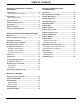
Table of Contents Section 1: Safety Rules & General Information Section 4: Maintenance and Troubleshooting Introduction ..................................................................1 Read This Manual Thoroughly ....................................1 Maintenance ...............................................................19 Safety Rules .................................................................1 How to Obtain Service .................................................
This page intentionally left blank.
Safety Rules & General Information Section 1: Safety Rules & General Information Introduction Thank you for purchasing a Generac Power Systems Inc. product. This unit has been designed to provide high performance, efficient operation, and years of use when maintained properly. The information in this manual is accurate based on products produced at the time of publication. The manufacturer reserves the right to make technical updates, corrections, and product revisions at any time without notice.
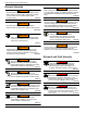
Safety Rules & General Information General Hazards WARNING WARNING Accidental Start-up. Disconnect the negative battery cable, then the positive battery cable when working on unit. Failure to do so could result in death or serious injury. (000130) Risk of injury. Do not operate or service this machine if not fully alert. Fatigue can impair the ability to service this equipment and could result in death or serious injury. (000215) WARNING WARNING Personal injury. Keep out of reach of children.
Safety Rules & General Information DANGER Risk of fire. Allow fuel spills to completely dry before starting engine. Failure to do so will result in death or serious injury. (000174) Fire Hazards WARNING Risk of Fire. Verify machine has properly cooled before installing cover and storing machine. Hot surfaces could result in fire. (000109) WARNING Fire risk. Fuel and vapors are extremely flammable. Do not operate indoors. Doing so could result in death, serious injury, or property or equipment damage.
Safety Rules & General Information Safety and Operating Decals This unit features numerous safety and operating decals. These decals provide important operating instructions and warn of dangers and hazards. Replace damaged or missing safety and operating decals immediately.
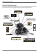
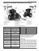
General Information and Setup Section 2: General Information and Setup B F C G A E L H D K J 006533 I 005812 A Throttle Lever E Belt Guard I B Start Key Switch F Operator Presence Lever J Starter Cord C Gas Fill G Brake Lever K Fuel Shut-Off D Oil Drain H Oil Fill/Check L Choke Lever Carbide Teeth Figure 2-1. Features and Controls Stump Grinder Specifications Engine Specifications Tire Size 14.5 in (36.
General Information and Setup Remove Contents from Carton 1. See Figure 2-2, Figure 2-3, Figure 2-4, and Figure 25. Remove and verify carton contents prior to assembly. Carton contents should contain the following: F K E G D B A C D J H 008070 Figure 2-4. Manual Caddy I A Item C B Description QTY 006017 A Manual Caddy 1 Figure 2-2.
General Information and Setup 2. Contact Generac Customer Service at 1-888-4363722 (1-888-GENERAC), or www.generac.com with the unit model and serial number for any missing carton contents. 3. Record model, serial number, and date of purchase on front cover of this manual. Assembly Instructions 1. See Figure 2-6. Loosen right wheel bolt (A) using a 1/2” wrench with the wheel on the ground. 8. Lower the machine to the ground and finish tightening the right wheel bolt with a 1/2" wrench. 9.
General Information and Setup 17. See Figure 2-10. Slip the barrel end of the brake cable into brake lever socket (L) then insert brake cable sheath (M) into the end of brake lever bracket (N). 22. See Figure 2-13. Pull up on brake cable (T) until resistance is felt and brake band touches brake drum. T N U M V 006027 L 006024 Figure 2-10. Installing Brake Cable 18. See Figure 2-11. Turn the top jam nut (O) up the brake cable threads. O Figure 2-13. Tightening the Jam Nuts 23.
General Information and Setup 31. See Figure 2-16. Plug the key switch connectors to either key switch terminal (X). X 36. See Figure 2-19. Tighten cable by holding engine throttle lever (D) in the IDLE position while pulling on cable sheath. D Y 006030 Figure 2-16. Key Switch Connector 32. Plug the black operator presence connector into the harness connector (Y). 33. See Figure 2-17. Move the cable tie (Z) securing the throttle cable to the right side handlebar up to the top portion of the handlebar.
General Information and Setup Maintenance Meter Installation Attaching Manual Caddy 1. Gently pry the black factory panel Insert from the control panel All product documents should be stored in the manual caddy. 2. Insert the panel adapter from the kit into the open hole in the control panel. Verify the adapter flange has engaged the panel completely. 1. See Figure 2-23. Attach caddy clamps (A) to right handlebar. 2.
General Information and Setup Assembling Hitch Adapter 1. See Figure 2-25. Secure hitch adapter (A) to tow bar (B) with two 3/8-16 x 1-1/4" bolts with 3/8” washers and two 3/8” locknuts with 3/8” washers (C) using two 9/16" wrenches. 2. See Figure 2-27. Remove oil dipstick/fill cap (A) and wipe dipstick clean. A C A 006035 B Figure 2-27. Oil Dipstick 008344 Figure 2-25. Assembling Hitch Adapter Assembling Trailer Hitch 1. See Figure 2-26.
General Information and Setup Adding Fuel Connecting Battery Cable DANGER Explosion and Fire. Fuel and vapors are extremely flammable and explosive. Add fuel in a well ventilated area. Keep fire and spark away. Failure to do so will result in death or serious injury. (000105) All units are shipped with the negative terminal battery cable disconnected. Before using the unit, connect the battery cable. 1. See Figure 2-30. Connect the negative (A) cable to the negative (-) terminal on the battery (B).
General Information and Setup Hitching Unit to Tow Vehicle Trailer Hitch 1. See Figure 2-34. Slide tow bar into tow bar adapter, align holes, and secure with linchpin (A). WARNING Personal injury. Never tow on roads. Towing on roads could result in death, serious injury, unit, or property damage. (000504) A WARNING Personal Injury. Remove tow bar from stump grinder before grinding stumps. Grinding stumps with tow bar installed could result in death, serious injury, or damage to property or the unit.
General Information and Setup High Altitude Replacement Kit At elevations above 8000 feet, the engine may experience decreased performance even with a high altitude kit At high altitude, a standard carburetor air-fuel mixture will be too rich. A rich mixture decreases performance, increases fuel consumption, fouls the spark plug and causes hard starting. Operation at high altitude, for extended periods of time, may increase emissions.
Operation Section 3: Operation Starting Engine WARNING Consult Manual. Read and understand manual completely before using product. Failure to completely understand manual and product could result in death or serious injury. (000100a) WARNING Personal injury. Never operate unit on slippery, wet, muddy, or icy surfaces. Doing so could result in death, serious injury, equipment or property damage. (000466) WARNING Personal injury. Always verify all guards and shields are in place prior to use.
Operation 4. As the engine warms up, slowly adjust the choke toward the OPEN position. Wait until the engine runs smoothly before each choke adjustment. 5. When the engine is warmed up and running smoothly, move the choke to the OPEN position. Electric Starting 1. See Figure 3-4. Verify the fuel shut-off (A) is in the OPEN position. 2. Move the choke control lever (B) to the CLOSED choke position. If the engine is warm leave the choke control lever in the OPEN position. Stopping Engine 1.
Operation 3. See Figure 3-7. Lock the hand brake (B) by engaging the brake lever (B), sliding the lock forward (C) and releasing the lever. 6. See Figure 3-9. Slowly move the cutter head to the left and through the front of the stump by pushing on the right hand handlebar .. B C 006043 006486 Figure 3-7. Brake Lock WARNING Personal injury. Verify cutting teeth do not touch any object before engaging the throttle lever.
Operation This page intentionally left blank.
Maintenance and Troubleshooting Section 4: Maintenance and Troubleshooting Maintenance Regular maintenance will improve performance and extend engine/equipment life. Regular maintenance, replacement, or repair of the emissions control devices and systems may be performed by any repair shop or person of the owner’s choosing. To obtain emissions control warranty service free of charge, contact Generac Customer Service at 1-888436-3722 (1-888-GENERAC), or www.generac.com. See the emissions warranty.
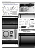
Maintenance and Troubleshooting Operating Maintenance Meter See Figure 4-1. The maintenance meter monitors accumulated running time, time until engine oil needs to be changed, and time until lubrication is recommended. Function button (A) cycles through the meter functions. 3. Pull the pre-cleaner off the paper filter assembly and shake the dirt from the foam pre cleaner and paper filter. 4. If the pre-cleaner or paper filter is too dirty to clean, clogged, or damaged, replace the parts.
Maintenance and Troubleshooting 1. See Figure 4-5. Place a waste oil container under oil drain plug (C). Replacing Belt WARNING Personal injury. Use appropriate personal protective equipment when working on unit. Failure to do so could result in death or serious injury. (000472) D 1. See Figure 4-7. Remove the three bolts and locknuts (A) from the belt guards with two 1/2" wrenches and remove the outer belt guard (B). C 006067 Figure 4-5. Oil Drain 2.
Maintenance and Troubleshooting Replacing Clutch 3. See Figure 4-10. Loosen locknut (A) on tooth (B) until the top of the locknut is flush with the top of tooth threads (C). WARNING Personal injury. Use appropriate personal protective equipment when working on unit. Failure to do so could result in death or serious injury. (000472) A C 1. Remove belt guard and belt. See Replacing Belt. 2. See Figure 4-9. Place a 5/8" wrench onto clutch bolt (A). Rotate wrench counterclockwise until resistance is felt.
Maintenance and Troubleshooting Replacing Cutting Teeth Adjusting Handlebars 1. Remove the left wheel. See Replacing Clutch. WARNING Personal injury. Use appropriate personal protective equipment when working on unit. Failure to do so could result in death or serious injury. (000472) 2. See Figure 4-15. Remove four bolts, lock washers and flat washers (A) from the brake drum with a 1/2" wrench and pull drum (B) from the axle. B CAUTION Equipment damage. Replace head assembly when damaged or worn.
Maintenance and Troubleshooting Replacing Wheels 1. See Figure 4-17. With the stump grinder on level ground remove the bolt, lock washer and flat washer from axle (A) with a 1/2" wrench. 3. Rotate the wheel forward and tighten the upper nut (C) until resistance is felt at the wheel. 4. Tighten the lower nut to the bracket. 5. Lower the unit to the ground and verify the left side wheel brakes when the brake lever is engaged.
Maintenance and Troubleshooting Ball Hitch Receiver Adjustment 1. See Figure 4-21. With 2" ball in receiver socket, close receiver latch completely. Verify locking trigger is engaged in detent. D Always recycle batteries in accordance with local laws and regulations. Contact your local solid waste collection site or recycling facility to obtain information on local recycling processes. For more information on battery recycling, visit the Battery Council International website at: http://batterycouncil.
Maintenance and Troubleshooting Replacing Battery 1. See Figure 4-22. Disconnect battery cables (A). 2. Remove the bolts and locknuts (C) securing the battery clamp (B) using two 7/16" wrenches. 3. Remove the clamp and the dead battery. 4. Install the new battery. 5. Install the battery clamp and secure clamp bolts and locknuts using two 7/16" wrenches. 6. Attach the black cable to the negative black terminal and the red cable to positive red terminal. B C A 006045 Figure 4-22.
Maintenance and Troubleshooting Symptom Possible Cause Inspect oil level and adjust as needed. Clean engine cooling fans and carburetor. Engine smokes Inspect air filter and replace if dirty or damaged. Contact Generac Customer Service at 1-888-436-3722, or www.generac.com Verify the choke lever is OPEN. Air filter may be dirty. Change as necessary. Engine lacks power or is not running smoothly. Spark plug may be dirty or cracked. Change as necessary. Refer to the engine owner’s manual Gas may be old.
Maintenance and Troubleshooting This page intentionally left blank.
Maintenance and Troubleshooting This page intentionally left blank.
Maintenance and Troubleshooting This page intentionally left blank.
Owner’s Manual for Stump Grinder 31
Part No. 10000024574 Rev. A 05/01/2018 ©2018 Generac Power Systems, Inc. All rights reserved Specifications are subject to change without notice. No reproduction allowed in any form without prior written consent from Generac Power Systems, Inc. 32 Generac Power Systems, Inc. S45 W29290 Hwy. 59 Waukesha, WI 53189 1-888-GENERAC (1-888-436-3722) www.generac.