Installation Manual Generac PWRcell™ Battery ON OFF BATTERY DISCONNECT 008980 WARNING Loss of life. This product is not intended to be used in a critical life support application. Failure to adhere to this warning could result in death or serious injury. (000209b) Register your Generac product at: https://pwrfleet.generac.com 1-888-GENERAC Register (888-436-3722) your Generac product at: WWW.GENERAC.COM Para español, visita: http://www.generac.
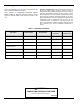
Use this page to record important information about your Generac Product Record the information found on your unit data label on this page. See Serial Number Locations. When contacting an Independent Authorized Service Dealer (IASD) or Generac Customer Service, always supply the complete model number and serial number of the unit. Operation and Maintenance: Proper maintenance and care of the energy storage system ensures a minimum number of problems and keeps operating expenses at a minimum.
Table of Contents Section 1: Safety Rules & General Information Introduction ..........................................................1 Read This Manual Thoroughly ....................................1 Safety Rules .........................................................1 How to Obtain Service .................................................1 General Hazards ..................................................2 Electrical Hazards ................................................
This page intentionally left blank.
Safety Rules & General Information Section 1: Safety Rules & General Information Introduction This installation manual provides instructions and recommendations for installing and commissioning the Generac PWRcell™ Battery. The PWRcell battery is designed to house compatible lithium ion battery modules, and connects directly to the PWRcell inverter and other REbus™- compatible components of the PWRcell system.
Safety Rules & General Information General Hazards DANGER Loss of life. Property damage. Installation must always comply with applicable codes, standards, laws and regulations. Failure to do so will result in death or serious injury. (000190) WARNING Electrocution. Potentially lethal voltages are generated by this equipment. Render the equipment safe before attempting repairs or maintenance. Failure to do so could result in death or serious injury. (000187) WARNING Equipment damage.
Safety Rules & General Information Electrical Hazards DANGER WARNING Electrocution. Never connect this unit to the electrical system of any building unless a licensed electrician has installed an approved transfer switch. Failure to do so will result in death or serious injury. (000150) DANGER Electrocution. Refer to local codes and standards for safety equipment required when working with a live electrical system. Failure to use required safety equipment could result in death or serious injury.
Safety Rules & General Information Battery Hazards General Rules DANGER WARNING Explosion. Do not dispose of batteries in a fire. Batteries are explosive. Electrolyte solution can cause burns and blindness. If electrolyte contacts skin or eyes, flush with water and seek immediate medical attention. (000162) WARNING DANGER Environmental Hazard. Always recycle batteries at an official recycling center in accordance with all local laws and regulations.
Safety Rules & General Information Standards Index WARNING Loss of life. This product is not intended to be used in a critical life support application. Failure to adhere to this warning could result in death or serious injury. (000209b) Strictly comply with all applicable national, state, and local laws, as well as codes or regulations pertaining to the installation of the system.
Safety Rules & General Information This page intentionally left blank.
General Information Section 2: General Information Specifications Description Units PWRcell 9 PWRcell 12 PWRcell 15 PWRcell 17 kWh 8.6 11.4 14.3 17.1 Continuous* kW 3.4 4.5 5.6 6.7 60 minutes** kW 4.2 5.6 7.0 8.4 2 minutes** kW 5.0 6.7 8.4 10.0 - 3 4 5 6 Energy Usable Energy Power Battery Modules Number DC Voltage (per module) VDC 46.8 (39-52) Communication Protocol - REbus DC nanogrid Voltage: Input/Output*** VDC 360-420 % 96.
General Information Serial Number Locations Unit Dimensions Refer to Figure 2-1 to locate serial numbers for the unit (A) and the individual battery modules (B). Record this information in Table 1: Important Information on the inside front cover of this manual so it is available if the tags are lost or damaged. When ordering parts or requesting assistance, you may be asked to provide this information. A B B C 0009892 Figure 2-2.
General Information About PWRcell Battery The PWRcell battery is the storage component of the PWRcell system. The battery can be used for gridconnected solar applications such as self-supply, rate arbitrage and clean backup power. The battery is designed to work seamlessly with Generac PV Links and the PWRcell inverter to form the PWRcell system for gridtied solar-plus-storage. All PWRcell products use the REbus 380VDC nanogrid to connect to each other.
General Information Component Locations ON Battery Disconnect Switch DANGER OFF BATTERY DISCONNECT A E B D Electrocution. Initiate a system-wide shutdown and turn the PWRcell Disconnect Switch OFF on all connected batteries before performing service. Failure to do so will result in death, serious injury, equipment and property damage. (000600) See Figure 2-4. Battery Disconnect switch (A) disconnects the battery string from the battery monitoring system (BMS) electronics.
Location and Compliance Section 3: Location and Compliance Location and Clearances Install the PWRcell battery in dwelling units in the following permitted locations only: • Attached garages separated from dwelling unit habitable spaces in accordance with local building code. • Detached garages and accessory structures. • Enclosed utility closets and storage or utility spaces. • Basements. NOTE: Refer to the local Building Code for permitted locations for commercial installations.
Location and Compliance Compliance Note on DC Wiring and the NEC DANGER Loss of life. Property damage. Installation must always comply with applicable codes, standards, laws and regulations. Failure to do so will result in death or serious injury. (000190) WARNING Electrocution. Refer to local codes and standards for safety equipment required when working with a live electrical system. Failure to use required safety equipment could result in death or serious injury. (000257) WARNING Equipment damage.
Installing Generac PWRcell Battery Section 4: Installing Generac PWRcell Battery Carton Contents • Wall bracket • Chassis (gray), including pre-installed electronics package and battery jumpers • Cover (white) • Hardware kit • Generac PWRcell Battery Installation Manual and Installing Battery Cabinet WARNING Personal Injury. Use caution when handling heavy parts and battery modules. Lift heavy parts in teams if necessary.
Installing Generac PWRcell Battery Battery Dimensions and Knockout Locations 9-7/8 in (25.1 cm) 22-3/16 in (56.3 cm) 1-5/16 in (3.3 cm) 57-5/8 in (146.3 cm) 13-3/8 in (34 cm) 9-3/8 in (23.9 cm) 1-1/4 in (3.12 cm) 41-5/8 in (105.7 cm) 67-5/8 in (1.7 m) 42-13/16 in (108.7 cm) 29-5/8 in (75.18 cm) Figure 4-1.
Installing Generac PWRcell Battery Placing Body onto Bracket and Leveling Feet 1. See Figure 4-2. Lift body (A) onto bracket (B). Keep body tight to the wall while lowering body onto bracket. Verify bracket tabs (C) hook into body pockets (D). D 6. 7. 8. C 9. Verify there is minimum 1-3/4 in (4.45 cm) gap between the bottom of the body and the floor. Tighten machine screws to bracket and torque to 13 in-lb (1.47 Nm). Verify feet have not lifted from floor. Tighten feet jam nuts to lock them in place.
Installing Generac PWRcell Battery To install REbus wiring: 1. See Figure 4-4. Install REbus conductors to their terminal blocks: RE+ to red (A), RE- to blue (B). 2. Install equipment grounding conductor to green terminal block (C). 3. If required, route field wiring conductors through the grommet wiring chase baffle (D). Connecting Blackstart Battery See Figure 4-5. Connect blackstart battery lead to battery terminal (E). NOTE: One lead is already connected to terminal (F).
Installing Generac PWRcell Battery Installing Rear Modules 1. 3. See Figure 4-7. Angle top of battery module (G) under and behind bracket lip (H). NOTE: Battery module ports (I) must face the right side of the PWRcell battery body with the COM ports above the power port. 2. 3. 4. See Figure 4-9. Install grounding tabs (L) at the top of the module on both sides. Fasten each grounding tab with a M4x8 mm SEMS screw (M) and torque to 13 in-lb (1.47 Nm).
Installing Generac PWRcell Battery Installing Module Spacer (PWRcell 9 and PWRcell 15 only) 1 See Figure 4-11. Module spacers (O) must be installed on any single module shelf. 2 009935 Figure 4-13. Installing Module Spacer (2 of 3) See Figure 4-14. Secure spacer with two M4X8 SEMS screws and torque to 13 in-lb (1.47 Nm). 4. O 009933 Figure 4-11. Module Spacer PWRcell modules and upgrade kits can be obtained by contacting Generac Customer Service at 1-888-4363722 (1-888-GENERAC), or www.generac.com.
Installing Generac PWRcell Battery See Figure 4-16. Note that there are three types of retainer clips: double retention clips (U), single retention clips marked O (T) and single retention clips marked X (S). • Install single retention clips (T) (S) at the top and 3. Connecting COM Cables 1. bottom of the stack. • Install double retention clips (U) between rows of modules. 2. 3. S T Secure retention clip to bracket with a M4X8 mm screw and torque to 13 in-lb (1.47 Nm). See Figure 4-18.
Installing Generac PWRcell Battery See Figure 4-19. Continue connecting the remaining battery modules. While installing CAT5 cables: 7. • Work from top to bottom • Connect battery modules sharing a shelf with a B A black jumper cable (I) going from the rear battery COM OUT port to the front battery COM IN port • Do not install a CAT5 cable to the last battery module’s COM OUT port (M) • Remaining COM cables can be left disconnected.
Installing Generac PWRcell Battery Installing Cover 1. 2. 3. Upgrading PWRcell Battery See Figure 4-23. Place cover (A) upright in front of unit. Slide cover straight back until it engages with body (B). Verify all angled guides are tucked inside body. The back edges of the cover should be against the rubber gasket along their entire length (C). See Figure 4-23. Inside of the PWRcell battery, battery modules are stacked 2-deep on three levels, allowing for up to 6 modules to be connected in a series.
Installing Generac PWRcell Battery 7. 8. Enable the PWRcell inverter. – Navigate to the inverter device page. – Select Enable. – Select Confirm. Perform Vset. – Navigate to the battery device page. – Select Start Vset. – Select Confirm. – Verify the battery is discharging. NOTE: The battery status LED on the front of the PWRcell battery unit will flash green when the battery is discharging and the inverter home screen will show power flowing from the battery. 9. 10.
Commissioning Section 5: Commissioning General Information NOTE: Register the PWRcell inverter are commissioning at https://pwrfleet.generac.com. Before commissioning PWRcell battery verify all wiring is correct and secure and that the front cover is securely in place.
Commissioning Decommissioning WARNING Environmental Hazard. Always recycle batteries at an official recycling center in accordance with all local laws and regulations. Failure to do so could result in environmental damage, death, or serious injury. (000228) WARNING Environmental Hazard. Decommissioning must be performed by qualified personnel. Decommissioning performed by unqualified personnel could result in environmental damage, death, or serious injury.
Troubleshooting Section 6: Troubleshooting General Troubleshooting Some of the more common problems are listed in the table below. This information is intended to be a check or verification that simple causes can be located and fixed. It does not cover all types of problems. Procedures that require in-depth knowledge or skills should be referred to a Generac Authorized Service Dealer. Table 6-1.
Troubleshooting This page intentionally left blank.
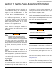
Section 7: Wiring Diagrams PWRcell 9 BLACK RED Contactors Battery String DC Snubber I/O Switch Black-start battery GRB REbus 380v DC REbus cable entrance Module CAT5 COMs Cable Module Spacer Module Jumpers Front Module 1 Module 2 Module 3 Top 009945 Back Installation Manual for Generac PWRcell Battery 27
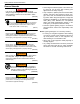
Wiring Diagrams PWRcell 12 BLACK RED Contactors Snubber Battery String DC I/O Switch Black-start battery GRB REbus 380v DC REbus cable entrance Module CAT5 COMs Cable Module 1 Module Jumpers Front Module 2 Module 4 Back 28 Module 3 Top 009946 Installation Manual for Generac PWRcell Battery
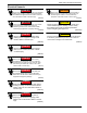
Wiring Diagrams PWRcell 15 BLACK RED Contactors Snubber Battery String DC I/O Switch Black-start battery GRB REbus 380v DC REbus cable entrance Module CAT5 COMs Cable Module Spacer Module Jumper Module 1 Module 2 Front Module 4 Module 5 Module 3 Top 009947 Back Installation Manual for Generac PWRcell Battery 29
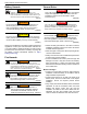
Wiring Diagrams PWRcell 17 BLACK RED Contactors Snubber Battery String DC I/O Switch Black-start battery GRB REbus 380v DC REbus cable entrance Module CAT5 COMs Cable Front Module 1 Module 3 Module 5 Module 2 Module 4 Module 6 Top Back 009948 30 Installation Manual for Generac PWRcell Battery
® Part No. DMAN00004 Rev. D 04/16/2020 ©2020 Generac Power Systems, Inc. All rights reserved. Specifications are subject to change without notice. No reproduction allowed in any form without prior written consent from Generac Power Systems, Inc. Generac Power Systems, Inc. S45 W29290 Hwy. 59 Waukesha, WI 53189 1-888-GENERAC (1-888-436-3722) www.generac.