® POWER SYSTEMS, INC.
INTRODUCTION Thank you for purchasing this model of the standby generator set product line by Generac Power Systems. Every effort was expended to make sure that the information and instructions in this manual were both accurate and current at the time the manual was written. However, the manufacturer reserves the right to change, alter or otherwise improve this product(s) at any time without prior notice.
Table of Contents Guardian Liquid-cooled 15 kW, 20 kW and 25 kW Generators INTRODUCTION ....................................IFC SAFETY RULES..........................................2 Section 3 OPERATION ..........................................11 Using a Standard “GTS” Transfer Switch ................11 Section 1 Control Console Components ..................................12 GENERAL INFORMATION ......................4 Manual Transfer and Startup ..................................13 Generator .....
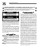
Important Safety Instructions Guardian Liquid-cooled 15 kW, 20 kW and 25 kW Generators SAVE THESE INSTRUCTIONS – The manufacturer suggests that these rules for safe operation be copied and posted in potential hazard areas. Safety should be stressed to all operators, potential operators, and service and repair technicians for this equipment. SAVE THESE INSTRUCTIONS – This manual contains important instructions that should be followed during installation and maintenance of the generator and batteries.
Important Safety Instructions Guardian Liquid-cooled 15 kW, 20 kW and 25 kW Generators • Inspect the generator regularly, and promptly repair or replace all worn, damaged or defective parts using only factory-approved parts. • Before performing any maintenance on the generator, disconnect its battery cables to prevent accidental start-up. Disconnect the cable from the battery post indicated by a NEGATIVE, NEG or (–) first. Reconnect that cable last. • Never use the generator or any of its parts as a step.
Section 1 - General Information Guardian Liquid-cooled 15 kW, 20 kW and 25 kW Generators GENERATOR AUTOMATIC SYSTEM OPERATION This equipment is a liquid-cooled, engine-driven generator set. The generator is designed to supply electrical power that operates critical electrical loads during utility power failure. The unit has been factory-installed in a weather resistant, all metal enclosure and is intended for outdoor installation only.
Section 1 - General Information Guardian Liquid-cooled 15 kW, 20 kW and 25 kW Generators Figure 1.2 - Main Circuit Breaker Model Rating Phase 004188 004189 004370 004371 004474 004475 15,000 15,000 20,000 20,000 25,000 25,000 1 1 1 1 1 1 Actual Current C/B Rating* 62.5 62.5 83.3 83.3 104.2 104.2 * Amp Rating of C/B structured 70 70 90 90 125 125 under model. % over rating Circuit Breaker 112% 112% 108% 108% 120% 120% 70A BQ2 70A BQ2 90A BQ2 90A BQ2 125A BQ2 125A BQ2 Figure 1.
Section 1 — General Information Guardian Liquid-cooled 15 kW, 20 kW and 25 kW Generators Figure 1.6 - Low Coolant Level Sensor DC FUSE This clearly labeled fuse is located on the front panel of the control system. It protects the panel wiring and components from damaging overload. Always remove this fuse before commencing work on the generator. The unit will not start or crank if the fuse is blown. Replace the fuse with one of the same size, type, and rating.
Section 1 — General Information Guardian Liquid-cooled 15 kW, 20 kW and 25 kW Generators ENGINE SPECIFICATIONS Make ..................................................................................Mitsubishi Displacement ....................................................92 inches3 (1.5 liters) Cylinder Arrangement ..........................................................4, in-line Valve Arrangement ....................................................Overhead Cam Firing Order ...........................
Section 2 — Installation Guardian Liquid-cooled 15 kW, 20 kW and 25 kW Generators STANDBY GENERATOR INSTALLATION Connecting this generator to an electrical system normally supplied by an electric utility shall be by means of a transfer switch, so as to isolate the electric system from the utility distribution system when the generator is operating.
Section 2 — Installation Guardian Liquid-cooled 15 kW, 20 kW and 25 kW Generators GENERATOR MOUNTING AND SUPPORT Retain the generator compartment to a concrete slab with 1/4-inch masonry type anchor bolts. Be sure the bolts are long enough to retain the compartment. The slab should be at least 6 inches thick and should extend beyond the enclosure to a distance of at least 3 inches on all sides. See pages 54-55 for generator major dimensions. BASIC STANDBY ELECTRIC SYSTEM Figure 2.
Section 2 — Installation Guardian Liquid-cooled 15 kW, 20 kW and 25 kW Generators GENERATOR AC NEUTRAL CONNECTIONS Generac uses an UNGROUNDED AC neutral. Grounding is recommended only at the main service entrance. If the neutral wire is grounded and one of the phase loads becomes grounded, the excessive current opens the load circuit breaker or collapses the generator field. The actual result depends on the electrical characteristics of the particular installed generator.
Section 3 - Operation The instructions in this section assume that the standby generator has been properly installed, serviced, tested, adjusted and otherwise prepared for use by a competent, qualified installation contractor. Be sure to read the “Safety Rules” on Pages 2 and 3, as well as all other safety information in this manual, before attempting to operate this (and related) equipment. Have the engine cooling system properly filled with the recommended coolant mixture.
Section 3 — Operation Guardian Liquid-cooled 15 kW, 20 kW and 25 kW Generators CONTROL CONSOLE COMPONENTS The components of a liquid-cooled generator control console (Figure 3.1) are as follows: Figure 3.1 - Liquid-Cooled Generator Panel HOURMETER Indicates time the engine-generator has operated, in hours and tenths of hours. Use the hourmeter along with the periodic maintenance schedule for your generator set.
Section 3 - Operation Guardian Liquid-cooled 15 kW, 20 kW and 25 kW Generators NOTE: This fuse will not remove the + battery input power from the PCB when it opens. This means the exercise timer will not be reset. If this fuse does open, carefully check the wiring to the start, fuel, field boost and transfer outputs before replacing the fuse.
Section 4 — Maintenance Guardian Liquid-cooled 15 kW, 20 kW and 25 kW Generators ENGINE HEATER Your Generac standby generator comes equipped with a block heater (Figure 4.1), similar to the block heaters used in automotive applications. The block heater is wired to a grounded plug. Figure 4.1 - Engine Block Heater E. EVERY 500 OPERATING HOURS 1.Service air cleaner. 2.Check starter. 3.Check engine DC alternator. F. EVERY 800 OPERATING HOURS 1.Retorque cylinder head. (See Torque Specs, page 7.) 2.
Section 4 — Maintenance Guardian Liquid-cooled 15 kW, 20 kW and 25 kW Generators • If oil level is below the dipstick ADD mark, remove oil fill cap. Add the recommended oil to bring oil level up to the FULL mark. DO NOT FILL ABOVE THE “FULL” MARK. See page 6 for recommended oils. Figure 4.2 - Oil Dipstick and Oil Fill Cap EXERCISE SYSTEM Start the generator engine at least once every seven days and let it run at least 20 minutes. See page 14, “Weekly Exercise Cycle”.
Section 4 — Maintenance Guardian Liquid-cooled 15 kW, 20 kW and 25 kW Generators Figure 4.4 – Engine Air Cleaner CHANGING ENGINE OIL Refer to maintenance performed by authorized service facilities for engine oil and filter change frequencies. Drain the oil while the engine is still warm from running. This means warm up the engine, shut it down and drain immediately as follows: 1. Remove OIL DRAIN HOSE from its retaining clip. 2. Loosen and remove OIL DRAIN HOSE CAP.
Section 4 — Maintenance Guardian Liquid-cooled 15 kW, 20 kW and 25 kW Generators MISCELLANEOUS MAINTENANCE CLEANING THE GENERATOR Keep your generator as clean and as dry as possible. Dirt and moisture that accumulates on internal generator windings have an adverse effect on insulation resistance. Periodically clean generator exterior surfaces. A soft brush may be used to loosen caked on dirt. You can use a vacuum system or dry, low pressure air to remove any accumulations of dirt.
Section 5 — Troubleshooting Guardian Liquid-cooled 15 kW, 20 kW and 25 kW Generators PERIODIC REPLACEMENT PARTS Part Name Oil Filter Radiator Cap Air Cleaner Spark Plug Generac’s Part Number # 0A45310244 # 046627 # 059402 # 0A45310275 TROUBLESHOOTING POINTS PROBLEM CAUSE CORRECTION Engine won’t crank. 1. 30 amp fuse blown. 2. Loose or corroded or defective battery cables. 3. Defective starter contactor. 4. Defective starter motor. 5. Dead or Defective Battery. 1. Replace fuse. 2.
Section 6 — Scheduled Maintenance Guardian Liquid-cooled 15 kW, 20 kW and 25 kW Generators Following is a recommended maintenance schedule for Generac Guardian small standby and residential generator sets. The established intervals in the schedule are the maximum recommended when the unit is used in an average service application. They will need to be decreased (performed more frequently) if the unit is used in a severe application.
Section 6 — Scheduled Maintenance Guardian Liquid-cooled 15 kW, 20 kW and 25 kW Generators Maintenance Tasks Level 1 Recommended to be done monthly/ 10 hrs. 1. Disable the unit from operating per the first page warning. 2. Check the engine oil level. Adjust as necessary. 3. Check the engine coolant level. Adjust as necessary. 4. Check the engine coolant thermal protection level. Correct as necessary. 5. Check the natural gas delivery system on gas engine driven units. Tighten connections as necessary. 6.
Section 6 — Scheduled Maintenance Guardian Liquid-cooled 15 kW, 20 kW and 25 kW Generators Maintenance Tasks Level 1 Recommended to be done monthly/ 10 hrs. Level 2 Task Comp. (DateInitials) Required to be done 3 months/ Break-in 30 hrs. Level 3 Task Comp. (DateInitials) Required to be done Semiannually/ 50 hrs. Level 4 Task Comp. (DateInitials) Required to be done Annually/ 100 hrs. Task Comp. (DateInitials) 13.
Section 7 - Electrical Data Guardian Liquid-cooled 15 kW, 20 kW and 25 kW Generators Wiring Diagram — Control Panel (1-Phase) —Drawing No. 0A2803-D 22 Generac® Power Systems, Inc.
Section 7 - Electrical Data Guardian Liquid-cooled 15 kW, 20 kW and 25 kW Generators Wiring Diagram — Control Panel (1-Phase) —Drawing No. 0A2803-D Generac® Power Systems, Inc.
Section 7 - Electrical Data Guardian Liquid-cooled 15 kW, 20 kW and 25 kW Generators Electrical Schematic — Control Panel (1-Phase) — Drawing No. 0A2802-B 24 Generac® Power Systems, Inc.
Section 7 - Electrical Data Guardian Liquid-cooled 15 kW, 20 kW and 25 kW Generators (AC OUTLET) Wiring Diagram — 1.5L Gas Engine — Drawing No. 0A7176-A Generac® Power Systems, Inc.
Section 7 - Electrical Data Guardian Liquid-cooled 15 kW, 20 kW and 25 kW Generators Electrical Schematic — 1.5L Gas Engine — Drawing No. 0A7182-A FED CIRCUIT (AC OUTLET) 26 Generac® Power Systems, Inc.
Section 8 - Exploded Views and Parts Guardian Liquid-cooled 15 kW, 20 kW and 25 kW Generators Exploded View – Enclosure (15 and 20 kW) — Drawing No. A7188-D ITEM PART NO. QTY. DESCRIPTION 1 2 3 4 5 6 7 97575 A3769 A3768 A5314 67042 22264 67035 2 2 1 1 2 6 6 8 9 82570 A7215 2 10 BRACE, SIDE DOOR, ENCLOSURE DOOR, ENCLOSURE TOP, ENCLOSURE LATCH LOCK WASHER, #8 SCREW, PAN HEAD MACH.-#8-32 x 5/16" PLUG-4" SWAGE FASTENER-W/NYLON WASHER ITEM 10 11 13 14 15 16 17 18 19 PART NO. QTY.
Section 8 - Exploded Views and Parts Guardian Liquid-cooled 15 kW, 20 kW and 25 kW Generators Exploded View – Enclosure (25kW) — Drawing No. 0C1404-B 28 Generac® Power Systems, Inc.
Section 8 - Exploded Views and Parts Guardian Liquid-cooled 15 kW, 20 kW and 25 kW Generators Exploded View – Enclosure (25kW) — Drawing No. 0C1404-B ITEM 1 2 3 4 5 6 7 8 9 10 11 12 13 14 15 16 17 18 19 20 21 23 24 25 26 27 28 29 30 31 32 36 37 38 39 40 42 43* 44* 45* 46* 47* 48* 49* 50* 51* 52* 53* 54 55 PART NO.
Section 8 - Exploded Views and Parts Guardian Liquid-cooled 15 kW, 20 kW and 25 kW Generators Exploded View – Control Panel (15 and 20 kW) — Drawing No. 0A2872-F 30 Generac® Power Systems, Inc.
Section 8 - Exploded Views and Parts Guardian Liquid-cooled 15 kW, 20 kW and 25 kW Generators Exploded View – Control Panel (15 and 20 kW) — Drawing No. 0A2872-F ITEM 1 2 3 4 5 6 7 8 9 10 11 12 13 14 15 16 17 18 19 20 21 22 23 24 25 26 27 28 29 30 31 32 33 34 35 PART NO.QTY.
Section 8 - Exploded Views and Parts Guardian Liquid-cooled 15 kW, 20 kW and 25 kW Generators Exploded View – Control Panel (25kW) — Drawing No. 0C8847-C 32 Generac® Power Systems, Inc.
Section 8 - Exploded Views and Parts Guardian Liquid-cooled 15 kW, 20 kW and 25 kW Generators Exploded View – Control Panel (25kW) — Drawing No. 0C8847-C ITEM 1 2 3 4 5 6 7 8 9 10 11 12 13 14 15 16 17 18 19 20 21 22 23 24 25 26 27 28 29 30 31 32 33 34 35 36 PART NO.QTY.
To engine bypass 21 6 9 7 7 32 "A" 23 8 8 11 5 20 To thermostat adapter 7 16 14 7 8 14 12 8 10 19 32 3 (Bottom only) 25 26 27 24 To water inlet tube (Midway up engine block) 12 13 8 17 To base of water inlet tube (On block) 2 10 "A" 29 31 33 3 12 4 24 14 30 12 4 18 17 34 33 11 Section 8 - Exploded Views and Parts 9 12 Guardian Liquid-cooled 15 kW, 20 kW and 25 kW Generators Exploded View – Radiator (15 & 20 kW) — Drawing No. A7206-C 34 Generac® Power Systems, Inc.
Section 8 - Exploded Views and Parts Guardian Liquid-cooled 15 kW, 20 kW and 25 kW Generators Exploded View – Radiator (15 & 20 kW) — Drawing No. A7206-C ITEM 1 2 3 4 5 6 7 8 9 10 11 12 13 14 15 16 17 18 19 20 21 22 23 24 25 26 27 28 29 30 31 32 33 34 PART NO. 0A6272 0A5734 0A6237 0A6238 084918 050967 057823 099502 083709 052250 042568 022097 049813 022473 084427 050967 075443 056892 0A6284 0A6258 029032 031669 060035 022127 022145 022129 045771 042907 076749 080712 0A7215 0A7275 0A2111 065852 QTY.
Section 8 - Exploded Views and Parts Guardian Liquid-cooled 15 kW, 20 kW and 25 kW Generators Exploded View – Radiator (25 kW) — Drawing No. 0C1406-B 36 Generac® Power Systems, Inc.
Section 8 - Exploded Views and Parts Guardian Liquid-cooled 15 kW, 20 kW and 25 kW Generators Exploded View – Radiator (25 kW) — Drawing No. 0C1406-B ITEM 2 3 4 5 6 7 8 9 11 12 13 14 15 16 17 18 19 20 21 22 23 24 25 26 27 28 29 30 31 32 33 34 35 36 37 PART NO.
Section 8 - Exploded Views and Parts Guardian Liquid-cooled 15 kW, 20 kW and 25 kW Generators Exploded View – Mounting Base (15 & 20 kW) — Drawing No. A7187-A ITEM 1 3 4 5 6 7 8 9 10 12 13 14 15 PART NO. C2632 70936 70936C 39253 22145 22129 45771 71956 51730 57821 21991 27482 A2308 QTY. 1 2 2 8 12 12 12 4 2 2 1 1 1 DESCRIPTION BASE, MOUNTING ISOLATOR-VIBRATION ISOLATOR, VIBRATION CAPSCREW, HEX HEAD-M8-1.25 x 20MM FLAT WASHER-M8 LOCK WASHER-M8 NUT, HEX-M8-1.
Section 8 - Exploded Views and Parts Guardian Liquid-cooled 15 kW, 20 kW and 25 kW Generators Exploded View – Mounting Base (25 kW) — Drawing No. 0C1405-A ITEM 1 3 4 5 6 7 8 9 10 12 13 14 15 PART NO. 0A9955 070936 070936C 039253 022145 022129 045771 071956 051730 057821 021991 027482 0A2308 QTY. 1 2 2 8 12 12 12 4 2 2 1 2 1 DESCRIPTION BASE MOUNTING DAMPENER VIBRATION DAMPENER VIBRATION SCREW HHC M8-1.25 X 20 G8.8 WASHER FLAT 5/16 ZINC WASHER LOCK M8-5/16 NUT HEX M8-1.
Section 8 - Exploded Views and Parts Guardian Liquid-cooled 15 kW, 20 kW and 25 kW Generators Exploded View – Muffler (15 & 20 kW) — Drawing No. A7618-B 3 5 1 4 2 12 11 12 9 10 9 8 9 13 13 7 6 15 14 ITEM 1 2 3 4 5 6 7 8 9 10 11 12 13 14 15 PART NO. 020689 060366 059933 080761 059939 075546A 036434 022259 022129 036449 076032 039253 045771 0C3683 0A7215 QTY. 1 1 1 1 1 1 1 2 6 1 1 4 4 1 4 DESCRIPTION MUFFLER W/RAIN SHLD MUFFLR STRAP 6IN DIA ELBOW 90 DEG 2 NPT NIPPLE TOE 2 NPT X 4.
Section 8 - Exploded Views and Parts Guardian Liquid-cooled 15 kW, 20 kW and 25 kW Generators Exploded View – Muffler (25 kW) — Drawing No. 0C1408-B ITEM 1 2 3 4 5 6 7 8 9 10 11 12 13 14 PART NO. 0A4355 0C1636 036434 036449 0C1330 0C1318 0C1068 0C1412 0A5728 060366 066889 022145 022129 045771 0A8974 QTY. 1 1 4 4 1 1 1 1 1 2 4 4 4 4 1 DESCRIPTION MANIFOLD EXHAUST 1.5L NIPPLE TOE 1.5 NPT X 6.5 BL IRON BOLT U 5/16-18 X 2.09 SADDLE 2 INCH PIPE EXHAUST FLEX PIPE EXHAUST SUPPORT MUFFLER 1.
Section 8 - Exploded Views and Parts Guardian Liquid-cooled 15 kW, 20 kW and 25 kW Generators Exploded View – Circuit Breaker — Drawing No. 0D8294 1 4 3 6 2 5 ITEM 1 2 3 4 5 6 PART NO. 0A2106 0A2952 039782 048373 039766 0A2077 023965 022264 QTY.
Section 8 - Exploded Views and Parts Guardian Liquid-cooled 15 kW, 20 kW and 25 kW Generators Exploded View – CMA Assembly — Drawing No. 081086-D ITEM PART NO. QTY. 1 2 3 4 5 6 7 8 9 10 11 074100 1 076009A 1 072566 080882 074978 047822 075476 083264 022985 022264 051787 079847 4 4 1 1 2 1 4 4 2 1 DESCRIPTION ASSY HOME STDBY LOGIC (MODELS 921, 863, 865) PP LOGIC ASM 50/60HZ (MODEL 9428) NUT SPACER .250 PCB SCREW PPH TAPPING #6X5/8 SS DECAL TERMINAL STRIP BLOCK TERM 20A 7 X 6 X 1100V SCREW PPHM M4-0.
Section 8 - Exploded Views and Parts Guardian Liquid-cooled 15 kW, 20 kW and 25 kW Generators Exploded View – Battery — Drawing No. 098922-E ITEM 1 2 3 4 5 6 7 8 9 10 11 12 13 14 15 PART NO. 077483 038804D 038805B 0742600131 022131 046526 052213 059567 078121 022145 022129 022259 050331A 050331 075763 QTY. 1 1 1 1 1 1 1 2 1 2 2 2 1 1 3 DESCRIPTION BATT 12VDC 75-AH 26/26R CABLE BATT RED #4 X 20.00 CABLE BATT BLK #4 X 23.00 ASSY,WIRE#16 RED 1.6 WASHER FLAT 3/8 ZINC WASHER LOCK M10 SCREW HHC M10-1.
Section 8 - Exploded Views and Parts Guardian Liquid-cooled 15 kW, 20 kW and 25 kW Generators Exploded View – Governor Assembly — Drawing No. 0A7216-A ITEM PART NO. QTY.
Section 8 - Exploded Views and Parts Guardian Liquid-cooled 15 kW, 20 kW and 25 kW Generators Exploded View – Generator — Drawing No. 0A9348-C 46 Generac® Power Systems, Inc.
Section 8 - Exploded Views and Parts Guardian Liquid-cooled 15 kW, 20 kW and 25 kW Generators Exploded View – Generator — Drawing No. 0A9348-C ITEM 1 2 3 4 5 6 7 8 9 10 11 12 13 14 15 16 17 18 19 20 21 22 23 24 25** 26* 27 28 29 30 31 32 33 35 PART NO.
Section 8 - Exploded Views and Parts Guardian Liquid-cooled 15 kW, 20 kW and 25 kW Generators Exploded View – Gaseous Fuel System — Drawing No. 0A9349-E 48 Generac® Power Systems, Inc.
Section 8 - Exploded Views and Parts Guardian Liquid-cooled 15 kW, 20 kW and 25 kW Generators Exploded View – Gaseous Fuel System — Drawing No. 0A9349-E ITEM 1 2 3 4 5 6 7 8 9 11 13 14 15 16 17 18 19 20 21 22 23 24 25 26 27 28 29 30 31 32 33 34 35 36 37 38 PART NO. QTY.
Section 8 - Exploded Views and Parts Guardian Liquid-cooled 15 kW, 20 kW and 25 kW Generators Exploded View – Engine Compartment — Drawing No. 0A7642-J 50 Generac® Power Systems, Inc.
Section 8 - Exploded Views and Parts Guardian Liquid-cooled 15 kW, 20 kW and 25 kW Generators Exploded View – Engine Compartment — Drawing No. 0A7642-J ITEM PART NO. QTY.
Section 9 — Installation Guardian Liquid-cooled 15 kW, 20 kW and 25 kW Generators Installation Drawing 15 & 20 kW – Drawing No. A7214-C 52 Generac® Power Systems, Inc.
Section 9 — Installation Air Intake Air Intake Air Outlet Guardian Liquid-cooled 15 kW, 20 kW and 25 kW Generators Installation Drawing 15 & 20 kW – Drawing No. A7214-C Generac® Power Systems, Inc.
Section 9 — Installation Guardian Liquid-cooled 15 kW, 20 kW and 25 kW Generators Installation Drawing 25 kW – Drawing No. 0C1450 54 Generac® Power Systems, Inc.
Section 9 — Installation Guardian Liquid-cooled 15 kW, 20 kW and 25 kW Generators Installation Drawing 25 kW – Drawing No. 0C1450 Air Intake Air Intake Air Intake Generac® Power Systems, Inc.
Section 10 – Warranty Guardian Liquid-cooled 15 kW, 20 kW and 25 kW Generators CALIFORNIA EMISSION CONTROL WARRANTY STATEMENT YOUR WARRANTY RIGHTS AND OBLIGATIONS The California Air Resources Board (CARB) and Generac Power Systems, Inc. (Generac) are pleased to explain the Emission Control System Warranty on your new engine.* In California, new utility, and lawn and garden equipment engines must be designed, built and equipped to meet the state’s stringent anti-smog standards.
Section 10 – Warranty Guardian Liquid-cooled 15 kW, 20 kW and 25 kW Generators EMISSION CONTROL SYSTEM WARRANTY Emission Control System Warranty (ECS Warranty) for 1995 and later model year engines: (a) Applicability: This warranty shall apply to 1995 and later model year engines. The ECS Warranty Period shall begin on the date the new engine or equipment is purchased by/delivered to its original, end-use purchaser/owner and shall continue for 24 consecutive months thereafter.
Section 10 – Warranty Guardian Liquid-cooled 15 kW, 20 kW and 25 kW Generators GENERAC POWER SYSTEMS "TWO YEAR" STANDARD WARRANTY FOR GUARDIAN® "PREPACKAGED EMERGENCY AUTOMATIC STANDBY GENERATORS" For a period of two years or 2000 hours of operation from the date of original sale, whichever occurs first, Generac Power Systems, Inc.