® POWER SYSTEMS, INC. Installation and Owner’s Manual Air-cooled, Prepackaged Automatic Standby Generators Models: 004692-0 (8.5 kW) GENERAC R POWER SYSTEMS, INC. R ! Not intended for use as Primary Power in place of utility or in lifesupport applications. DANGER DEADLY EXHAUST FUMES.
INTRODUCTION Thank you for purchasing this model of the Centurion product line by Generac Power Systems Inc. This model is a compact, high performance, aircooled, engine-driven generator designed to automatically supply electrical power to operate critical loads during a utility power failure. This unit is factory installed in an all-weather, metal enclosure that is intended exclusively for outdoor installation.
Table of Contents Air-cooled 8.5 kW Generator Introduction ........................Inside Front Cover 3.5 Read This Manual Thoroughly ........................IFC Contents ..........................................................IFC Operation and Maintenance ............................IFC How to Obtain Service ....................................IFC Manual Transfer Operation ........................14 3.5.1 Transfer to Generator Power Source......................................14 3.5.
IMPORTANT SAFETY INSTRUCTIONS Air-cooled 8.5 kW Generator SAVE THESE INSTRUCTIONS – The manufacturer suggests that these rules for safe operation be copied and posted near the unit’s installation site. Safety should be stressed to all operators and potential operators of this equipment. ! ! WARNING: ! GENERAL HAZARDS ! ! The engine exhaust from this product contains chemicals known to the state of California to cause cancer, birth defects or other reproductive harm.
IMPORTANT SAFETY INSTRUCTIONS Air-cooled 8.5 kW Generator ELECTRICAL HAZARDS • All generators covered by this manual produce dangerous electrical voltages and can cause fatal electrical shock. Utility power delivers extremely high and dangerous voltages to the transfer switch as does the standby generator when it is in operation. Avoid contact with bare wires, terminals, connections, etc., while the unit is running.
Section 1 — General Information Air-cooled 8.5 kW Generator 1.3 Only qualified electricians or contractors should attempt such installations, which must comply strictly with applicable codes, standards and regulations. 1.1 UNPACKING/INSPECTION After unpacking, carefully inspect the contents for damage. • This standby generator set has been factory supplied with a weather protective enclosure that is intended for outdoor installation only.
Section 1 — General Information Air-cooled 8.5 kW Generator 1.4 YOUR GENERATOR Figure 1.1 – 8.5 kW, V-Twin GT-990 Engine Oil Dipstick Data Decal Air Filter Control Panel Exhaust Enclosure Fuel Regulator 12 Volt Battery Oil Filter Generac® Power Systems, Inc.
Section 1 — General Information Air-cooled 8.5 kW Generator 1.5 SPECIFICATIONS 1.5.1 GENERATOR Rated Max. Continuous Power Capacity (Watts*) Rated Voltage Rated Max. Continuous Load Current (Amps) 120 Volts 240 Volts Main Line Circuit Breaker Phase Number of Rotor Poles Rated AC Frequency Power Factor Battery Requirement Weight Output Sound Level Normal Operating Range Model 004692 8,500 NG/8,500 LP 120/240 70.8 NG/70.8 LP 35.4 NG/35.
Section 1 — General Information Air-cooled 8.5 kW Generator 1.6 FUEL REQUIREMENTS AND RECOMMENDATIONS With LP gas, use only the vapor withdrawal system. This type of system uses the vapors formed above the liquid fuel in the storage tank. The engine has been fitted with a fuel carburetion system that meets the specifications of the 1997 California Air Resources Board for tamper-proof dual fuel systems. The unit will run on natural gas or LP gas, but it has been factory set to run on natural gas.
Section 1 — General Information Air-cooled 8.5 kW Generator 1.9 LOCATION ◆ 1.9.1 GENERATOR Install the generator set, in its protective enclosure, outdoors, where adequate cooling and ventilating air is always available. Consider these factors: • Install the unit where air inlet and outlet openings will not become obstructed by leaves, grass, snow, etc. If prevailing winds will cause blowing or drifting, you may need to consider using a windbreak to protect the unit.
Section 2 — Post Installation Start-up and Adjustments Air-cooled 8.5 kW Generator amps for 8.5 kW at -17.8º C (0º F) minimum. When using a maintenance-free battery, it is not necessary to check the specific gravity or electrolyte level. Have these procedures performed at the intervals specified in the “Service Schedule.” A negative ground system is used. Battery connections are shown on the wiring diagrams. Make sure the battery is correctly connected and terminals are tight.
Section 2 — Post Installation Start-up and Adjustments Air-cooled 8.5 kW Generator 2. Turn OFF all loads connected to the transfer switch terminals T1 and T2. 3. Turn on the utility power supply to the transfer switch using the means provided (such as a utility main line circuit breaker). DANGER 4. 5. 6. 7. 8. The transfer switch is now electrically “hot.” Contact with “hot” parts will result in extremely hazardous and possibly fatal electrical shock. Proceed with caution.
Section 2 — Post Installation Start-up and Adjustments Air-cooled 8.5 kW Generator 15. Set the Auto/Off/Manual switch to OFF. The engine should shut down. 2.5 CHECKING AUTOMATIC OPERATION To check the system for proper automatic operation, proceed as follows: 1. Check that the Auto/Off/Manual switch is set to OFF. 2. Turn OFF the utility power supply to the transfer switch, using the means provided (such as a utility main line circuit breaker). 3.
Section 2 — Post Installation Start-up and Adjustments Air-cooled 8.5 kW Generator ◆ 2.7.1 Do not make any unnecessary adjustments. Factory settings are correct for most applications. However, when making adjustments, be careful to avoid overspeeding the engine. If this procedure or equipment are not available to you, locate the Generac Dealer nearest you and they can perform the adjustments. ! NOTE: A service fee may be charged for this adjustment. 2.
Section 3 — Operation Air-cooled 8.5 kW Generator 3.1 BREAK-IN PROCEDURE 3.2.3 “MANUAL” POSITION Once the unit has been installed and all electrical checks have been made, it is strongly recommended that the following “Break-in Procedure” be completed to ensure correct generator operation in the future. Set the switch to MANUAL to crank and start the engine. Transfer to standby power will not occur unless there is a utility failure. 1. Set the generator’s Auto/Off/Manual switch to AUTO. 2.
Section 3 — Operation Air-cooled 8.5 kW Generator 3.4 SEQUENCE OF AUTOMATIC OPERATION The generator’s control panel houses a control logic circuit board. This board constantly monitors utility power source voltage. Should that voltage drop below a preset level, circuit board action will signal the engine to crank and start.
Section 3 — Operation Air-cooled 8.5 kW Generator 3.5.2 TRANSFER BACK TO UTILITY POWER SOURCE When utility power has been restored, you will want to transfer back to that source and shut down the generator. This can be accomplished as follows: 1. Set the generator’s main circuit breaker to its OFF (or open) position. 2. Let the engine run for a minute or two at no-load to stabilize the internal temperatures. 3. Set the generator’s Auto/Off/Manual switch to its OFF (or open) position.
Section 4 — Maintenance Air-cooled 8.5 kW Generator 3.7.3 OVERCRANK Figure 4.1 – Generator Control Panel This feature prevents the generator from damaging itself when it continually attempts to start and another problem, such as no fuel supply, prevents it from starting. The unit will crank and rest for a preset time limit. Then, it will stop cranking, and the LED on the generator control panel will light indicating an overcrank failure.
Section 4 — Maintenance Air-cooled 8.5 kW Generator 4.3 CHANGING THE ENGINE OIL 4.3.1 Figure 4.3 – Oil Drain Hose and Filter ENGINE OIL RECOMMENDATIONS Use oil of American Petroleum Institute (API) Service Class SG, SH or SJ. Use all season SAE 5W-30 Synthetic oil. Organic break-in oil is required before using synthetic oil. NOTE: The unit is supplied with “break-in” oil. See the “Break-in Procedure,” Section 3.1 (Page 13), for the first required oil change.
Section 4 — Maintenance Air-cooled 8.5 kW Generator Figure 4.4 — 12 kW and 15 kW Engine Air Cleaner Screw Cover 4.7 BATTERY MAINTENANCE The battery should be inspected per the “Service Schedule,” Section 4.11 (Page 19). The following procedure should be followed for inspection: 1. Inspect the battery posts and cables for tightness and corrosion. Tighten and clean as necessary. 2. Check the battery fluid level of unsealed batteries and, if necessary, fill with DISTILLED WATER ONLY.
Section 4 — Maintenance Air-cooled 8.5 kW Generator Lead-acid batteries present a risk of fire because they generate hydrogen gas. The following procedures are to be followed: Figure 4.6 - Valve Clearance Adjustment • DO NOT SMOKE when near the battery; • DO NOT cause flame or spark in battery area; and • Discharge static electricity from your body before touching the battery by first touching a grounded metal surface.
Section 4 — Maintenance Air-cooled 8.5 kW Generator 4.11.2 RETURN TO SERVICE ! The maximum ambient temperature for your generator is 48.9° C (104° F). 4.10 ATTENTION AFTER SUBMERSION If the generator has been submerged in water, it MUST NOT be started and operated. Following any submersion in water, have a Generac Authorized Dealer thoroughly clean and dry the generator. 4.11 OUT OF SERVICE PROCEDURE 4.11.
Section 4 — Maintenance Air-cooled 8.5 kW Generator 4.13 SERVICE SCHEDULE ATTENTION: It is recommended that all service work be performed by your nearest Generac Authorized Dealer. SYSTEM/COMPONENT X = Action R = Replace as Necessary * = Notify Dealer if Repair is Needed.
Section 5 — Troubleshooting Air-cooled 8.5 kW Generator 5.1 TROUBLESHOOTING GUIDE PROBLEM CAUSE CORRECTION The engine will not crank. 1. Fuse blown 2. Loose, corroded or defective battery cables 3. Defective starter contactor 4. Defective starter motor 5. Dead Battery 1. Replace fuse. 2. Tighten, clean or replace as necessary. 3. * 4. * 5. Charge or replace battery. The engine cranks but will not start. 1. Out of fuel 2. Defective fuel solenoid (FS) 3. Open #14 wire from engine control board 4.
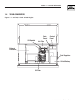
CBHOM-F CBHOM-F CBHOM-F CBHOM-F CBHOM-F TYPE HOM 120/240v TYPE HOM 120/240v TYPE HOM 120/240v TYPE HOM 120/240v TYPE HOM 120/240v M6PEM-T M6PEM-T LEFT SIDE VIEW 622 [24.5"] 604 [23.5"] 76.2mm [3.00"] PEA GRAVEL MINUMUM 704 [27.7"] 207 [8.14"] TRANSFER SWITCH M6PEM-T CBHOM-F TYPE HOM 120/240v 716 [28"] 743 [29.
Section 7 — Electrical Data Air-cooled 8.5 kW Generator Wiring Diagram - Drawing No.
Section 7 — Electrical Data Air-cooled 8.5 kW Generator Wiring Diagram - 8.5 kW – Drawing No.
Section 7 — Electrical Data Air-cooled 8.5 kW Generator Electrical Schematic - Drawing No.
Section 7 — Electrical Data Air-cooled 8.5 kW Generator Electrical Schematic - Drawing No.
Section 8 — Exploded Views and Parts Lists Air-cooled 8.5 kW Generator Compartment – Drawing No.
Section 8 — Exploded Views and Parts Lists Air-cooled 8.5 kW Generator Compartment – Drawing No. 0D8445-A ITEM PART NO. QTY.
Section 8 — Exploded Views and Parts Lists 31 28 10 27 28 17 32 31 28 13 11 23 5 24 38 7 21 34 12 33 39 6 8 4 9 31 37 40 38 3 20 14 2 22 15 1 19 10 17 32 10 19 32 30 25 24 16 26 29 36 28 18 29 35 36 41 32 42 41 Air-cooled 8.5 kW Generator Engine & Alternator – Drawing No. 0D8446 30 Generac® Power Systems, Inc.
Section 8 — Exploded Views and Parts Lists Air-cooled 8.5 kW Generator Engine & Alternator – Drawing No. 0D8446 ITEM PART NO. QTY.
Section 8 — Exploded Views and Parts Lists Air-cooled 8.5 kW Generator Engine – Drawing No.
Section 8 — Exploded Views and Parts Lists Air-cooled 8.5 kW Generator Engine – Drawing No. 0D8674-C Part 1 ITEM 1 PART NO. QTY.
Section 8 — Exploded Views and Parts Lists Air-cooled 8.5 kW Generator Engine – Drawing No. 0D8674-C Part 2 74 138 75 122 124 76 139 125 135 136 123 77 137 120 125 79 124 133 78 132 131 119 80 134 115 116 127 114 117 121 81 130 82 118 97 98 126 99 96 95 83 128 129 100 102 84 86 85 88 89 109 103 93 87 105 104 94 97 98 99 112 90 110 106 101 89 91 92 107 112 108 112 113 111 34 Generac® Power Systems, Inc.
Section 8 — Exploded Views and Parts Lists Air-cooled 8.5 kW Generator Engine – Drawing No. 0D8674-C Part 2 ITEM PART NO. QTY.
Section 8 — Exploded Views and Parts Lists Air-cooled 8.5 kW Generator Control Panel Assembly – Drawing No. 0D8503-B 41 8,9 8,32 40 27 10 22 38 1 43 6 25 7 31 33 23 37 38 27 45 16 29 28 48 42 49 12 4 2 29 28 44 20 47 45 24 11 47 45 44 21 17 45 15 35 14 30 39 46 36 29 28 3 19 14 15 35 49 17 13 23 16 21 34 15 14 5 36 Generac® Power Systems, Inc.
Section 8 — Exploded Views and Parts Lists Air-cooled 8.5 kW Generator Control Panel Assembly – Drawing No. 0D8503-B ITEM 1 2 3 4 5 6 7 8 9 10 11 12 13 14 15 16 17 18 19 20 21 PART NO. QTY.
Section 8 — Exploded Views and Parts Lists Air-cooled 8.5 kW Generator GTS Load Center – Drawing No. 0D3996-C 12 31 37 7 9 17 18 6 36 39 22 16 23 30 9 27 15 13 1 2 3 29 10 5 4 4 24 11 19 25 22 40 42 16 21 23 26 14 38 41 8 33 32 35 34 34 ITEM PART NO. QTY.
Section 8 — Exploded Views and Parts Lists Air-cooled 8.5 kW Generator Regulator – Drawing No. 0D8720-B 10 8 7 34 33 2 6 36 21 5 10 20 37 32 4 37 3 25 24 23 10 1 22 35 FOR GT 760 ENGINE ONLY 19 16 26 29 18 15 14 12 11 28 17 19 13 27 31 32 12 23 22 26 15 14 11 25 29 18 20 16 17 28 24 13 9 21 ITEM 1 2 3 4 5 6 7 8 9 10 11 12 13 14 15 16 17 18 19 20 PART NO.
Section 9 – Warranty Air-cooled 8.5 kW Generator NOTE: This Emission Control Warranty Statement pertains to this product only IF the generator size is 15 kW or below. CALIFORNIA EMISSION CONTROL WARRANTY STATEMENT YOUR WARRANTY RIGHTS AND OBLIGATIONS The California Air Resources Board (CARB) and Generac Power Systems, Inc. (Generac) are pleased to explain the Emission Control System Warranty on your new engine.
Section 9 – Warranty Air-cooled 8.5 kW Generator EMISSION CONTROL SYSTEM WARRANTY Emission Control System Warranty (ECS Warranty) for 1995 and later model year engines: (a) Applicability: This warranty shall apply to 1995 and later model year engines. The ECS Warranty Period shall begin on the date the new engine or equipment is purchased by/delivered to its original, end-use purchaser/owner and shall continue for 24 consecutive months thereafter.
Section 9 – Warranty Air-cooled 8.5 kW Generator GENERAC POWER SYSTEMS "TWO YEAR" STANDARD WARRANTY FOR "PREPACKAGED EMERGENCY AUTOMATIC STANDBY GENERATORS" ® For a period of two years or 2000 hours of operation from the date of original sale, whichever occurs first, Generac Power Systems, Inc.