CENTURION ® Installation and Owner’s Manual Air-cooled, Prepackaged Automatic Standby Generators Models: 004692-2 (8.5 kW) GENERAC R POWER SYSTEMS, INC. R ® CENTURION *This manual should remain with the unit.* ! Not intended for use as Primary Power in place of utility or in life-support applications. DANGER DEADLY EXHAUST FUMES.
INTRODUCTION Thank you for purchasing this model of the Centurion product line by Generac Power Systems Inc. This model is a compact, high performance, aircooled, engine-driven generator designed to automatically supply electrical power to operate critical loads during a utility power failure. This unit is factory installed in an all-weather, metal enclosure that is intended exclusively for outdoor installation.
Table of Contents Air-cooled 8.5 kW Generator Introduction ........................Inside Front Cover 3.2.2 “Off” Position ....................................14 Read This Manual Thoroughly ........................IFC Contents ..........................................................IFC Operation and Maintenance ............................IFC How to Obtain Service ....................................IFC 3.2.3 “Manual” Position ............................14 3.3 Automatic Transfer Operation ..........
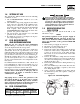
IMPORTANT SAFETY INSTRUCTIONS Air-cooled 8.5 kW Generator SAVE THESE INSTRUCTIONS – The manufacturer suggests that these rules for safe operation be copied and posted near the unit’s installation site. Safety should be stressed to all operators and potential operators of this equipment. ! ! WARNING: ! GENERAL HAZARDS ! ! The engine exhaust from this product contains chemicals known to the state of California to cause cancer, birth defects or other reproductive harm.
IMPORTANT SAFETY INSTRUCTIONS Air-cooled 8.5 kW Generator ELECTRICAL HAZARDS • All generators covered by this manual produce dangerous electrical voltages and can cause fatal electrical shock. Utility power delivers extremely high and dangerous voltages to the transfer switch as does the standby generator when it is in operation. Avoid contact with bare wires, terminals, connections, etc., while the unit is running.
Section 1 — General Information Air-cooled 8.5 kW Generator There are LED readouts on the control panel to notify personnel that one of these faults has occurred. DANGER ! 1.1 Only qualified electricians or contractors should attempt such installations, which must comply strictly with applicable codes, standards and regulations. UNPACKING/INSPECTION After unpacking, carefully inspect the contents for damage.
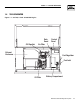
Section 1 — General Information Air-cooled 8.5 kW Generator 1.4 THE GENERATOR Figure 1.1 – 8.5 kW, V-Twin GT-990/760 Engine Oil Dipstick Data Decal Air Filter Exhaust Enclosure Control Panel Fuel Regulator Fuel Inlet Oil Filter Battery Compartment Generac® Power Systems, Inc.
Section 1 — General Information Air-cooled 8.5 kW Generator 1.5 SPECIFICATIONS 1.5.1 GENERATOR Rated Max. Continuous Power Capacity (Watts*) Rated Voltage Rated Max. Continuous Load Current (Amps) 120 Volts 240 Volts Main Line Circuit Breaker Phase Number of Rotor Poles Rated AC Frequency Power Factor Battery Requirement at -17.8° C (0° F) Weight Output Sound Level Normal Operating Range Model 004692 8,500 NG/8,500 LP 120/240 70.8 NG/70.8 LP 35.4 NG/35.
Section 1 — General Information Air-cooled 8.5 kW Generator 1.6 SYSTEM SET LED The “System Set” LED is lit when all of the following conditions are true: 1. The AUTO/OFF/MANUAL switch is set to the AUTO position. 2. The UTILITY voltage being supplied to the unit is being sensed by the PCB. If the UTILITY sense voltage is not connected to the unit or if it is below 168 volts AC, then the System Set light will flash rapidly.
Section 1 — General Information Air-cooled 8.5 kW Generator 9. Apply thread sealant to the threads of the hose fitting and replace it into the regulator body. 10. Re-attach the small hose and hose clamp and tighten as necessary. 11. Replace the engine air in baffle using the four M6 screws. 12. Identify both brass adjustment screws on the regulator.
Section 1 — General Information Air-cooled 8.5 kW Generator Figure 1.5 – Battery Cable Connections • • • • Remove watches, rings or other metal objects; Use tools with insulated handles; Wear rubber gloves and boots; Do not lay tools or metal parts on top of the battery; and • Disconnect charging source prior to connecting or disconnecting battery terminals. ! Do not open or mutilate the battery. Released electrolyte has been known to be harmful to the skin and eyes, and to be toxic.
Section 2 — Post Installation Start-up and Adjustments Air-cooled 8.5 kW Generator 2.1 BEFORE INITIAL START-UP Before starting, complete the following: 1. Set the generator's AUTO/OFF/MANUAL switch to the OFF position. 2. Turn OFF the utility power supply to the transfer switch using the means provided (such as the utility main line circuit breaker). 3. Turn OFF all loads connected to the tranfer switch terminals T1 and T2. 4.
Section 2 — Post Installation Start-up and Adjustments Air-cooled 8.5 kW Generator 2.4 GENERATOR TESTS UNDER LOAD To test the generator set with electrical loads applied, proceed as follows: 1. Set generator’s main circuit breaker to its OFF (or open) position. 2. Turn OFF all loads connected to the transfer switch terminals T1 and T2. 3. Set the generator's AUTO/OFF/MANUAL switch to OFF. 4.
Section 2 — Post Installation Start-up and Adjustments Air-cooled 8.5 kW Generator 3. Turn on appliances, lights, pumps, etc., that are on the emergency circuits in an attempt to fully load the generator. Be cautious not to overload the generator. Use the following chart as a guide: Unit 8.5 kW 120 Volts 70.8 amps 240 Volts 35.4 amps 4. When full load has been achieved. Connect a frequency meter to the output lugs of the generator’s main line circuit breaker. 5.
Section 3 — Operation Air-cooled 8.5 kW Generator Figure 2.4 — Full Load Speed Adjust Screw Full Load Speed Adjust Screw ◆ 2.7.1 ADDITIONAL CORROSION PROTECTION Periodically spray all engine linkage parts and brackets with corrosion inhibiting spray such as WD-40 or a comparable product. 2.8 VOLTAGE REGULATOR ADJUSTMENT With the frequency between 62-63 Hertz, slowly turn the slotted potentiometer (Figure 2.5) until line voltage reads 244-252 volts.
Section 3 — Operation Air-cooled 8.5 kW Generator 3.2.2 “OFF” POSITION This switch position shuts down the engine. This position also prevents automatic operation. 3.2.3 “MANUAL” POSITION Set the switch to Manual to crank and start the engine. Transfer to standby power will not occur unless there is a utility failure. ! 3.3 With the switch set to AUTO, the engine may crank and start at any time without warning.
Section 3 — Operation Air-cooled 8.5 kW Generator DANGER 4. 5. 6. 7. Do not attempt to activate the transfer switch manually until all power voltage supplies to the switch have been positively turned off. Failure to turn off all power voltage supplies may result in extremely hazardous and possibly fatal electrical shock. Use the manual transfer handle inside the transfer switch to move the main contacts to their “Standby” position, i.e., loads connected to the standby power source (Figure 3.2).
Section 4 — Maintenance Air-cooled 8.5 kW Generator 3.7 PROTECTION SYSTEMS 3.7.1 LOW OIL PRESSURE SWITCH This switch (Figure 3.3) has normally closed contacts that are held open by engine oil pressure during cranking and operating. Should oil pressure drop below the 8 psi range, switch contacts close, and the engine shuts down. The unit should not be restarted until oil is added. The AUTO/OFF/MANUAL switch must then be turned to OFF and then back to AUTO. 3.7.
Section 4 — Maintenance Air-cooled 8.5 kW Generator 2. Remove the dipstick and wipe it dry with a clean cloth. 3. Install the dipstick; then, remove it again. The oil level should be at the dipstick “Full” mark. If necessary, add oil to the “Full” mark only. DO NOT FILL ABOVE THE “FULL” MARK. Never operate the engine with the oil level below the “Add” mark on the dipstick. Doing this could damage the engine. 4. Install the dipstick. 5. Reset the AUTO/OFF/MANUAL switch to its original position. ! 2.
Section 4 — Maintenance Air-cooled 8.5 kW Generator 5. Install the cover. Turn the two cover screws clockwise to tighten. See the “Service Schedule,” Section 4.11 for air cleaner maintenance. See Section 1.5.1 for air filter replacement part number. Figure 4.4 — V-twin Engine Air Cleaner Screw 4.7 BATTERY MAINTENANCE The battery should be inspected per the “Service Schedule,” Section 4.11. The following procedure should be followed for inspection: 1.
Section 4 — Maintenance Air-cooled 8.5 kW Generator • DO NOT SMOKE when near the battery; • DO NOT cause flame or spark in battery area; and • Discharge static electricity from body before touching the battery by first touching a grounded metal surface. ! Figure 4.6 - Valve Clearance Adjustment Jam Nut Pivot Ball Stud Rocker Arm Valve Stem Be sure the AUTO/OFF/MANUAL switch is set to the OFF position before connecting the battery cables.
Section 4 — Maintenance Air-cooled 8.5 kW Generator 4.10 ATTENTION AFTER SUBMERSION 4.11.2 RETURN TO SERVICE If the generator has been submerged in water, it must not be started and operated. Following any submersion in water, have a Generac Authorized Dealer thoroughly clean and dry the generator. To return the unit to service after storage, proceed as follows: 4.11 OUT OF SERVICE PROCEDURE 4.11.
Section 4 — Maintenance Air-cooled 8.5 kW Generator 4.13 SERVICE SCHEDULE ATTENTION: It is recommended that all service work be performed by the nearest Generac Authorized Dealer. SYSTEM/COMPONENT X = Action R = Replace as Necessary * = Notify Dealer if Repair is Needed.
Section 5 — Troubleshooting Air-cooled 8.5 kW Generator 5.1 TROUBLESHOOTING GUIDE PROBLEM CAUSE CORRECTION The engine will not crank. 1. Fuse blown 2. Loose, corroded or defective battery cables 3. Defective starter contactor 4. Defective starter motor 5. Dead Battery 1. Replace fuse. 2. Tighten, clean or replace as necessary. 3. * 4. * 5. Charge or replace battery. The engine cranks but will not start. 1. Out of fuel 2. Defective fuel solenoid (FS) 3. Open #14 wire from engine control board 4.
716 [28 743 [29 M6PEM M6P M6PEM-T PE T LEFT SIDE VIEW 622 [24.5"] 604 [23.5"] 76.2mm [3.00"] PEA GRAVEL MINUMUM 704 [27.7"] 207 [8.14"] TRANSFER SWITCH (IF SUPPLIED) 308 [12"] FRONT VIEW 1232 [48.5"] 1193 [47"] "DO NOT LIFT BY THE ROOF" LIFTING HOLES 4-CORNERS Ø30.2mm [Ø1.19"] 149 [5.9"] RIGHT SIDE VIEW 490.7 [ AIR 260 [10.2"] **ALL DIMENSIONS IN: MILLIMETERS [INCHES] REAR VIEW ROUNDING LUG CABLE ACCESS HOLES.
Section 7 — Electrical Data Air-cooled 8.5 kW Generator Wiring Diagram - Drawing No.
Section 7 — Electrical Data Air-cooled 8.5 kW Generator Wiring Diagram - 8.5 kW – Drawing No.
Section 7 — Electrical Data Air-cooled 8.5 kW Generator Electrical Schematic - Drawing No.
Section 7 — Electrical Data Air-cooled 8.5 kW Generator Electrical Schematic - Drawing No.
Section 7 — Electrical Data Air-cooled 8.5 kW Generator Electrical Schematic - 12 Circuit Load Center - Drawing No.
Section 7 — Electrical Data Air-cooled 8.5 kW Generator Electrical Schematic - 12 Circuit Load Center - Drawing No.
Section 7 — Electrical Data Air-cooled 8.5 kW Generator Wiring Diagram - 12 Circuit Load Center - Drawing No. 0E7687 30 Generac® Power Systems, Inc.
Section 7 — Electrical Data Air-cooled 8.5 kW Generator Wiring Diagram - 12 Circuit Load Center - Drawing No. 0E7687 Generac® Power Systems, Inc.
Section 8 — Exploded Views and Parts Lists Air-cooled 8.5 kW Generator Enclosure – Drawing No. 0F0100-A 76 44 85 80 71 77 69 41 48 82 79 80 68 40 81 30 17 72 1 86 72 73 5 52 18 A 29 12 44 49 16 19 75 89 64 28 55 47 54 50 46 35 11 49 8 74 51 9 35 27 50 22 56 49 49 35 1 25 14 57 5 59 62 59 13 34 38 26 3 51 39 37 43 42 36 49 2 43 51 21 83 32 33 49 10 53 52 20 4 50 62 15 71 69 35 63 25 60 32 Generac® Power Systems, Inc.
Section 8 — Exploded Views and Parts Lists Air-cooled 8.5 kW Generator Compartment – Drawing No. 0F0100-A ITEM PART NO. QTY.
Section 8 — Exploded Views and Parts Lists 28 27 28 17 13 11 2 5 24 38 7 21 34 12 33 39 6 8 9 31 37 32 31 28 40 38 3 20 14 2 22 15 1 19 10 17 32 10 19 32 30 25 16 29 36 35 36 18 29 42 10 41 31 36 32 5 36 Air-cooled 8.5 kW Generator Engine & Alternator – Drawing No. 0D8446-C 34 Generac® Power Systems, Inc.
Section 8 — Exploded Views and Parts Lists Air-cooled 8.5 kW Generator Engine & Alternator – Drawing No. 0D8446-C ITEM PART NO. QTY.
36 Generac® Power Systems, Inc. 42 40 38 45 44 143 37 46 43 29 32 52 55 51 26 50 47 48 49 3 140 24 33 35 36 53 30 25 54 56 23 34 34 58 57 59 16A 60 18 17 16B 16A 22 61 63 62 15 64 20 14 13 71 72 27, 28, 29 73 3, 32, 33, 34, 35, 36, 40, 72 65 66 2, 5, 19, 20, 39, 40, 47, 64, 93, 140 8 12 1 10 2 7 9 6 143 5 4 Section 8 — Exploded Views and Parts Lists Air-cooled 8.5 kW Generator Engine – Drawing No.
Section 8 — Exploded Views and Parts Lists Air-cooled 8.5 kW Generator Engine – Drawing No. 0E8774-G Part 1 ITEM 1 PART NO. QTY.
Section 8 — Exploded Views and Parts Lists Air-cooled 8.5 kW Generator Engine – Drawing No. 0E8774-G Part 2 74 138 75 122 124 76 139 125 135 136 123, 145 77 120 137 125 79 124 133 78 32 134 119 143 80 116 142 115 127 114 11 121 81 8 29 118 97 8 130 126 99 96 95 83 102 84 109 103 105 86 85 88 89 110 99 1 90 101 89 91 92 107 112 108 112 113 111 38 Generac® Power Systems, Inc.
Section 8 — Exploded Views and Parts Lists Air-cooled 8.5 kW Generator Engine – Drawing No. 0E8774-G Part 2 ITEM 74 75 76 77 78 79 80 81 82 83 84 85 86 87 88 89 90 91 92 93 94 95 96 97 98 99 100 101 102 103 104 105 106 107 108 109 PART NO. QTY.
Section 8 — Exploded Views and Parts Lists 5 44 17 35 29 22 37 8,9 38 27 40 Generac® Power Systems, Inc. 19 46 10 47 45 44 48 49 6 38 7 21 2 4 17 49 23 27 13 2 33 40 15 20 49 43 45 39 21 1 41 15 35 3 11 30 47 45 24 45 31 47 Air-cooled 8.5 kW Generator Control Panel Assembly – Drawing No.
Section 8 — Exploded Views and Parts Lists Air-cooled 8.5 kW Generator Control Panel Assembly – Drawing No. 0E7974-F ITEM 1 PART NO. QTY.
Section 8 — Exploded Views and Parts Lists Air-cooled 8.5 kW Generator GTS Load Center – Drawing No. 0E7973-B 12 31 37 7 9 6 11 5 2 3A 9 30 36 24 10 22 16 27 15 13 1 3 19 3B 20 26 17 22 16 21 23 40 18 38 14 8 33 32 38 34 34 42 Generac® Power Systems, Inc.
Section 8 — Exploded Views and Parts Lists Air-cooled 8.5 kW Generator GTS Load Center – Drawing No. 0E7973-B ITEM 1 2 3 3A 3B 3C 3D 4 5 6 7 8 9 10 11 12 13 14 15 16 17 18 19 20 21 22 23 24 25 26 27 28 29 30 31 32 33 34 35 36 37 38 39 40 PART NO. QTY.
Section 8 — Exploded Views and Parts Lists 21 13 17 6 13 26 44 Generac® Power Systems, Inc. 11 28 10 32 12 20 25 24 23 22 19 17 12 28 10 15 14 11 3 27 31 4 2 5 16 29 18 7 8 1 26 15 14 37 16 9 30 19 22 10 23 29 18 24 11 25 12 20 28 Air-cooled 8.5 kW Generator Regulator – Drawing No.
Section 8 — Exploded Views and Parts Lists Air-cooled 8.5 kW Generator Regulator – Drawing No. 0D8720-D ITEM 1 2 3 4 5 6 7 8 9 10 11 12 13 14 15 16 17 18 19 20 21 22 23 24 25 26 27 28 29 30 31 32 37 PART NO. 0D5694 0F3154 0C4647 0D4166 0C6070 043180 022264 075475 0C5760E 0C6606 097934 0C4645 0C5761 0C5968 0C6066 0C5759 0C5764 0C5764A 070728 0C6069 0C5762 045764 0C6731 0C6067 0C4706 0C6068 0C4643A 026073 026073 0A4032 0D3308 024310 028414A 0D5698A 0D3973 QTY.
Section 9 — Notes Air-cooled 8.5 kW Generator 46 Generac® Power Systems, Inc.
Section 9 — Notes Air-cooled 8.5 kW Generator Generac® Power Systems, Inc.
Section 10 – Warranty Air-cooled 8.5 kW Generator NOTE: This Emission Control Warranty Statement pertains to this product only IF the generator size is 15 kW or below. CALIFORNIA EMISSION CONTROL WARRANTY STATEMENT YOUR WARRANTY RIGHTS AND OBLIGATIONS The California Air Resources Board (CARB) and Generac Power Systems, Inc. (Generac) are pleased to explain the Emission Control System Warranty on your new engine.
Section 10 – Warranty Air-cooled 8.5 kW Generator EMISSION CONTROL SYSTEM WARRANTY Emission Control System Warranty (ECS Warranty) for 1995 and later model year engines: (a) Applicability: This warranty shall apply to 1995 and later model year engines. The ECS Warranty Period shall begin on the date the new engine or equipment is purchased by/delivered to its original, end-use purchaser/owner and shall continue for 24 consecutive months thereafter.
Section 10 – Warranty Air-cooled 8.5 kW Generator GENERAC POWER SYSTEMS "TWO YEAR" LIMITED WARRANTY FOR CENTURION "PREPACKAGED EMERGENCY AUTOMATIC STANDBY GENERATORS" For a period of two years from the date of original sale, Generac Power Systems, Inc.