Owner’s Manual Liquid-cooled, Prepackaged Standby Generators Model Number: 004988-1 This manual should remain with the unit.
INTRODUCTION Thank you for purchasing this model of the standby generator set product line by Generac Power Systems. Every effort was expended to make sure that the information and instructions in this manual are both accurate and current at the time the manual was written. However, the manufacturer reserves the right to change, alter or otherwise improve this product(s) at any time without prior notice.
Table of Contents Guardian Liquid-cooled 27 kW and 30 kW Generators INTRODUCTION ................................................IFC SAFETY RULES ....................................................2 Section 3 — OPERATION ................................12 3.1 Using a Standard “GTS” Transfer Switch............12 3.2 Control Console Components..............................12 Section 1 — GENERAL INFORMATION ............4 3.3 Manual Transfer and Startup ..............................13 1.
IMPORTANT SAFETY INSTRUCTIONS Guardian Liquid-cooled 27 kW and 30 kW Generators ! SAVE THESE INSTRUCTIONS – The manufacturer suggests that these rules for safe operation be copied and posted in potential hazard areas. Safety should be stressed to all operators, potential operators, and service and repair technicians for this equipment. ! SAVE THESE INSTRUCTIONS – This manual contains important instructions that should be followed during installation and maintenance of the generator and batteries.
IMPORTANT SAFETY INSTRUCTIONS Guardian Liquid-cooled 27 kW and 30 kW Generators • Inspect the generator regularly, and promptly repair or replace all worn, damaged or defective parts using only factory-approved parts. • Before performing any maintenance on the generator, disconnect its battery cables to prevent accidental start-up. Disconnect the cable from the battery post indicated by a NEGATIVE, NEG or (–) first. Reconnect that cable last. • Never use the generator or any of its parts as a step.
Section 1 - General Information Guardian Liquid-cooled 27 kW and 30 kW Generators 1.1 GENERATOR 1.3 This equipment is a liquid-cooled, engine-driven generator set. The generator is designed to supply electrical power that operates critical electrical loads during utility power failure. The unit has been factory-installed in a weather resistant, all metal enclosure and is intended for outdoor installation only.
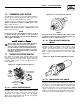
Section 1 - General Information Guardian Liquid-cooled 27 kW and 30 kW Generators 1.6 GENERATOR FUEL SYSTEM Figure 1.4 - Low Oil Pressure Switch The unit has been factory tested and adjusted using a natural gas fuel system. If propane (LP) gas is necessary, contact an authorized service dealer. Fuel pressure for a natural gas set up should be five inches to 14 inches of water column (0.18 to 0.5 psi) at all load ranges.
Section 1 — General Information Guardian Liquid-cooled 27 kW and 30 kW Generators Figure 1.6 - Low Coolant Level Sensor 1.7.7 LOW BATTERY The engine control board continually monitors the battery voltage and turns on the low battery LED if the battery voltage falls below 11.0 VDC for one minute. Low battery voltage is a non-latching alarm, which will automatically clear if the battery voltage rises above 11.0 VDC.
Section 1 — General Information Guardian Liquid-cooled 27 kW and 30 kW Generators Fuel pressure for a natural gas set up should be five inches to 14 inches of water column (0.18 to 0.5 psi) at all load ranges. 1.10 SPECIFICATIONS 1.10.1 GENERATOR SPECIFICATIONS Single-phase Model Rated Max. Cont. AC Power Output (kW) Rated voltage (volts) No.
Section 2 — Installation Guardian Liquid-cooled 27 kW and 30 kW Generators 1.13 TORQUE SPECIFICATIONS Cylinder Head ............................................15 (+ 90° + 90°) ft.lb. Intake Manifold ................................................................13 ft.lb. Exhaust Manifold..............................................................13 ft.lb. 1.14 ENGINE OIL RECOMMENDATIONS The unit has been filled with 5W-20 engine oil at the factory.
Section 2 — Installation Guardian Liquid-cooled 27 kW and 30 kW Generators • NFPA No. 220, STANDARD TYPES OF BUILDING CONSTRUCTION • NFPA No. 68, GUIDE FOR EXPLOSION VENTING • NFPA No. 70, NATIONAL ELECTRICAL CODE. • NFPA No. 30, FLAMMABLE AND COMBUSTIBLE LIQUIDS CODE. • NFPA No. 10, INSTALLATION, MAINTENANCE AND USE OF PORTABLE FIRE EXTINGUISHERS. 2.1.
Section 2 — Installation Guardian Liquid-cooled 27 kW and 30 kW Generators • It must have an ampere rating equal to the total amperage rating of the emergency distribution panel circuit. • Have it installed between the building’s main distribution panel and the emergency distribution panel. 2.6 TOTAL CIRCUIT ISOLATION METHOD When a generator capable of powering all electrical loads in the circuit is to be installed, use the “Total Circuit Isolation Method.
Section 2 — Installation Guardian Liquid-cooled 27 kW and 30 kW Generators 2.10 BATTERY INSTALLATION DANGER ! ! ! Standby generators installed with automatic transfer switches will crank and start automatically when NORMAL (UTILITY) source voltage is removed or is below an acceptable preset level.
Section 3 — Operation Guardian Liquid-cooled 27 kW and 30 kW Generators 2.11.4 GENERATOR SET LUBRICATION Check the engine crankcase oil level before operating and add oil to the proper level – the dipstick “FULL” mark. Never operate the engine with the oil level below the dipstick “ADD” mark. See “Specifications” (Section 1.10) and “Engine Oil Recommendations” (Section 1.14). NOTE: This engine is shipped from the manufacturer with 5W-20 oil. This oil should be changed after 30 hours of operation. 2.
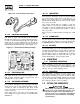
Section 3 - Operation Guardian Liquid-cooled 27 kW and 30 kW Generators Figure 3.1 - Home Standby Generator Panel LED INDICATORS: FLASHING GREEN LED = NO UTILITY SENSE 5 FLASHING RED LED'S = EXERCISER NOT SET (IN AUTO MODE ONLY) SOLID GREEN LED = SYSTEM READY, UTILITY POWER ON RED LED'S = INDIVIDUAL FAULT (SEE OWNER'S MANUAL FOR COMPLETE LED DETAILS) F F F OVER CRANK E US RED LED E US AUTO OFF ON SET EXERCISE TIME 3.2.
Section 3 — Operation Guardian Liquid-cooled 27 kW and 30 kW Generators 6. Adjust differential pot to make the recovery to load changes even faster and minimize load change undershoot and overshoot. If it is set too high it may introduce oscillations at some load. It can be set to zero (full CCW) if a small amount causes oscillations at some load. • Set the AUTO/OFF/MANUAL switch to its AUTO position. • Set the generator main circuit breaker to its ON or CLOSED position. Figure 3.
Section 4 — Maintenance Guardian Liquid-cooled 27 kW and 30 kW Generators 4.1 MAINTENANCE PERFORMED BY AUTHORIZED SERVICE FACILITIES A. EVERY THREE MONTHS 1. 2. 3. 4. 5. 6. Check battery state of charge and condition. Inspect and test fuel system. Check transfer switch. Inspect exhaust system. Check engine ignition system. Check fan belts. B. ONCE EVERY SIX MONTHS 1. Test Engine Safety Devices (low oil pressure, low coolant level, high coolant temperature). C. ONCE ANNUALLY 1. Test engine governor.
Section 4 — Maintenance Guardian Liquid-cooled 27 kW and 30 kW Generators 4.4.3 ENGINE COOLANT Check coolant level in coolant recovery bottle. See Specifications, Section 1.10. • Add recommended coolant mixture as necessary. • Periodically remove radiator pressure cap to make sure the coolant recovery system is functioning properly. Coolant should be at bottom of radiator filler neck. If coolant level is low, inspect gasket in radiator pressure cap. Replace cap, if necessary.
Section 4 — Maintenance Guardian Liquid-cooled 27 kW and 30 kW Generators 7. Start engine and check for oil leaks. Figure 4.2 - Oil Filter 3. Check the spark plug gap using a wire feeler gauge. Adjust the gap to 0.5-0.6 mm (0.020-0.025 inch) by carefully bending the ground electrode (Figure 4.4). Figure 4.4 – Setting the Spark Plug Gap SET PLUG GAP AT 0.5-0.6 mm (0.020-0.025 inch) OIL FILTER 4.5.
Section 4 — Maintenance Guardian Liquid-cooled 27 kW and 30 kW Generators • DO NOT recharge a weak battery while it is installed in the generator. Remove battery from generator and recharge in a well-ventilated area, away from fuel vapors, sparks, heat or flames. • Battery electrolyte fluid is an extremely caustic sulfuric solution that can cause severe burns. DO NOT permit fluid to contact eyes, skin, clothing, painted surfaces, wiring insulation, etc.
Section 4 — Maintenance Guardian Liquid-cooled 27 kW and 30 kW Generators 4.7 SCHEDULED MAINTENANCE Following is a recommended maintenance schedule for Generac small standby and residential generator sets. The established intervals in the schedule are the maximum recommended when the unit is used in an average service application. They will need to be decreased (performed more frequently) if the unit is used in a severe application.
Section 4 — Maintenance Guardian Liquid-cooled 27 kW and 30 kW Generators Maintenance Tasks Level 1 Recommended to be done monthly/ 10 hrs. 1. Disable the unit from operating per the first page warning. 2. Check the engine oil level. Adjust as necessary. 3. Check the engine coolant level. Adjust as necessary. 4. Check the engine coolant thermal protection level. Correct as necessary. 5. Check the natural gas delivery system on gas engine driven units. Tighten connections as necessary. 6.
Section 4 — Maintenance Guardian Liquid-cooled 27 kW and 30 kW Generators Maintenance Tasks Level 1 Recommended to be done monthly/ 10 hrs. Level 2 Task Comp. (DateInitials) Required to be done 3 months/ Break-in 30 hrs. Level 3 Task Comp. (DateInitials) Required to be done Semiannually/ 50 hrs. Level 4 Task Comp. (DateInitials) Required to be done Annually/ 100 hrs. Task Comp. (DateInitials) 13.
Section 5 — Troubleshooting Guardian Liquid-cooled 27 kW and 30 kW Generators TROUBLESHOOTING POINTS PROBLEM CAUSE CORRECTION Engine won’t crank. 1. 15 amp fuse blown. 2. Loose or corroded or defective battery cables. 3. Defective starter contactor. 4. Defective starter motor. 5. Dead or Defective Battery. 6. 4 amp fuse blown. 1. Replace fuse. 2. Tighten, clean or replace battery cables as necessary. 3. Replace contactor. 4. Replace starter motor. 5. Remove, change or replace battery. 6. Replace fuse.
Section 6 — Installation Diagram Guardian Liquid-cooled 27 kW and 30 kW Generators Installation Diagram — Drawing No. 0E8695 Generac® Power Systems, Inc.
Section 7 - Electrical Data Guardian Liquid-cooled 27 kW and 30 kW Generators Wiring Diagram — Engine — Drawing No.
Section 7 - Electrical Data Guardian Liquid-cooled 27 kW and 30 kW Generators Wiring Diagram — Engine — Drawing No.
Section 7 - Electrical Data Guardian Liquid-cooled 27 kW and 30 kW Generators Electrical Schematic — Engine — Drawing No. 0E6200-A ALTERNATOR ROTOR ALTERNATOR STATOR AUTOMATIC VOLTAGE REGULATOR BRUSH ASSEMLY (GENERATOR) BATTERY CHARGER BATTERY CAHRGE WINDING CIRCUIT BREAKER (OUTPUT) CIRCUIT BREAKER (EXCITATION) DIODE [FIELD BOOST] DISPLACED PHASE EXCITATION LEGEND {CONT.]: F1 FUSE, BAT. POWER (15A AGC TYPE) F2 FUSE, B/C (4A AGC TYPE) ICT TERMINAL BLOCK, INTERCONNECT.
Section 7 - Electrical Data Guardian Liquid-cooled 27 kW and 30 kW Generators Electrical Schematic — Engine — Drawing No.
16 28 Generac® Power Systems, Inc. 7 6 5 2 4 3 ENGINE FOOT 12 13 17 9 35 18 16 8 40 3 36 30 16 43 44 TO ENGINE BLOCK 34 35 41 38 18 44 32 33 22 42 20 31 20 7 6 5 37 15 1 13 14 12 11 REAR BEARING CARRIER HARNESS WIRE TO STARTER CONTACTOR TO STARTER BOLT TO ENGINE 18 BLOCK 14 16 10 4 3 2 Section 8 - Exploded Views and Parts Guardian Liquid-cooled 27 kW and 30 kW Generators Mounting Base — Drawing No.
Section 8 - Exploded Views and Parts Guardian Liquid-cooled 27 kW and 30 kW Generators Mounting Base — Drawing No. 0E6266-E ITEM 1 2 3 4 5 6 7 8 9 10 11 12 13 14 15 16 17 18 20 21 22 23 * 24 * 25 * 26 * 30 31 32 33 34 35 36 37 38 39 40 41 42 43 44 PART NO.
30 Generac® Power Systems, Inc. 3 30 31 LATCH DETAIL 38 32 4 34 18 17 43 27 2 41 4 37 35 25 RADIATOR SUPPORT 53 4 33 4 STATES FOAM IS ON FAR SIDE STATES FOAM IS ON NEAR SIDE 5555 53 44 4 4 4 13 11 9 SEE LATCH DETAIL 26 5588 TO "A" TYPICAL OF ROOF PANEL THAT REQUIRE INSULATION. SECURE AS SHOWN.
Section 8 - Exploded Views and Parts Guardian Liquid-cooled 27 kW and 30 kW Generators Compartment — Drawing No. 0E8333-D ITEM 1 2 3 4 5 6 7 8 9 10 11 12 13 14 15 16 17 18 19 20 21 22 23 24 25 26 27 28 29 30 31 32 33 34 35 36 37 38 39 40 41 42 43 44 50 * 51 52 53 54 55 56 57 58 59 PART NO.
Section 8 - Exploded Views and Parts Guardian Liquid-cooled 27 kW and 30 kW Generators Control Panel — Drawing No. 0E7118-G 32 Generac® Power Systems, Inc.
Section 8 - Exploded Views and Parts Guardian Liquid-cooled 27 kW and 30 kW Generators Control Panel — Drawing No. 0E7118-G ITEM PART NO. QTY. 1 2 3 4 5 6 7 8 9 10 11 12 13 14 15 16 0E7195 0E7196 0E7197 0E7193 0E7194 0E4494 082573 032300 022676 067682B 060015 054199 0C2657 099076 040213 0E9668 0E4905 1 1 1 1 1 1 1 2 1 1 1 1 1 1 2 1 1 17 18 19 20 21 067680 0E6875A 0E6881 * 0C5139 * 0E5142 * 1 1 REF. REF. REF.
Section 8 - Exploded Views and Parts Guardian Liquid-cooled 27 kW and 30 kW Generators Engine — Drawing No. 0E8170-J 69 27 28 57 58 14 1 15 60 10 8 25 61 36 35 38 42 2 55 43 47 51 54 36 3 42 35 34 36 43 35 7 42 40 36 35 3 37 6 78 12 5 BAFFLE REAR UPPER 21 43 11 47 38 26 7 73 29 2 57 31 58 60 48 44 30 61 24 36 35 39 25 31 32 48 17 39 45 35 64 42 65 41 66 68 GROUND WIRE 79 34 Generac® Power Systems, Inc.
Section 8 - Exploded Views and Parts Guardian Liquid-cooled 27 kW and 30 kW Generators Engine — Drawing No. 0E8170-J ITEM PART NO. QTY.
Section 8 - Exploded Views and Parts 15 FRAME 9 8 3 36 Generac® Power Systems, Inc. 11 10 9 12 "A" 27 20 15 1 4 21 3 12 TO WATER PUMP 24 22 24 2 6 17 7 12 TO ENGINE 5 13 12 18 14 TO "A" Guardian Liquid-cooled 27 kW and 30 kW Generators Radiator — Drawing No.
Section 8 - Exploded Views and Parts Guardian Liquid-cooled 27 kW and 30 kW Generators Radiator — Drawing No. 0E8528-B ITEM 1 2 3 4 5 6 7 8 9 10 11 12 13 14 15 17 18 20 21 22 23 24 25 26 27 PART NO. 0E9947 0E6340 0E8531 0E6398 0E6397 080713 076749 049814 022131 046526 045772 035685 0E8562 058443 0C2454 048031C 029032 046627 069811 065852 0A2111 052250 035461 0C7649 069860C QTY. 1 1 2 1 1 1 1 4 8 4 4 4 1 4 9 1 1 1 1 1 1 2 1 1 1 DESCRIPTION RADIATOR R-IN,L-OUT 658X489X49 VENTURI 3.
Section 8 - Exploded Views and Parts 15 38 Generac® Power Systems, Inc. 5 16 2 4 10 29 32 30 29 11 17 6 1 7 9 31 29 6 8 3 ANER 13 18 26 27 19 "B" 2 21 39 Guardian Liquid-cooled 27 kW and 30 kW Generators Fuel System — Drawing No.
Section 8 - Exploded Views and Parts Guardian Liquid-cooled 27 kW and 30 kW Generators Fuel System — Drawing No. 0E8190-B ITEM PART NO.
Section 8 - Exploded Views and Parts 12 15 7 17 4 1 18 31 30 5 LEADS 2 6 7 9 21 8 3 10 11 * 20 19 14 Guardian Liquid-cooled 27 kW and 30 kW Generators Alternator — Drawing No. 0E8660-B 40 Generac® Power Systems, Inc.
Section 8 - Exploded Views and Parts Guardian Liquid-cooled 27 kW and 30 kW Generators Alternator — Drawing No. 0E8660-B ITEM PART NO. QTY.
Section 8 - Exploded Views and Parts Guardian Liquid-cooled 27 kW and 30 kW Generators Muffler — Drawing No. 0E6479-D 9 13 5 13 7 10 11 13 12 6 10 11 TO COMPARTMENT 13 12 TO MANIFOLD 22 11 2 17 8 1 21 4 8 8 20 TO MANIFOLD 2 19 20 17 8 18 21 3 19 20 19 18 ITEM 1 2 3 4 5 6 7 8 9 10 PART NO. QTY. 0E6134 0E6464 0E6465 0E6465A 0E5914 1 2 1 1 1 060366 027837 036797 039253 022145 1 1 4 2 2 DESCRIPTION MUFFLER, 3.0L FORD EXHAUST ELBOW 3.0L FORD HSB EXHAUST PIPE LH 3.
Section 8 - Exploded Views and Parts Guardian Liquid-cooled 27 kW and 30 kW Generators Air Cleaner — Drawing No. 0E8189 ITEM PART NO. QTY. 1 2 3 4 5 0E5193 0E8200 0E8201 036434 0E0519A 1 1 1 1 1 6 7 8 9 10 0C8127 0A5547 062974 022127 037561 1 1 1 1 1 DESCRIPTION PLATE AIR CLEANER ADAPTER TUBE AIR INTAKE 3.0L FORD BRACKET AIR INTAKE 3.0L FORD BOLT U 5/16-18 X 2.
Section 9 - Notes Guardian Liquid-cooled 27 kW and 30 kW Generators 44 Generac® Power Systems, Inc.
Section 9 - Notes Guardian Liquid-cooled 27 kW and 30 kW Generators Generac® Power Systems, Inc.
Section 10 – Warranty Guardian Liquid-cooled 27 kW and 30 kW Generators GENERAC POWER SYSTEMS "TWO YEAR" LIMITED WARRANTY FOR GUARDIAN® "PREPACKAGED EMERGENCY AUTOMATIC STANDBY GENERATORS" For a period of two years from the date of original sale, Generac Power Systems, Inc. (Generac) warrants that its Guardian generator will be free from defects in material and workmanship for the items and period set forth below.