Owner’s Manual Liquid-cooled, Prepackaged Standby Generators Model Number: 004988-2 This manual should remain with the unit.
INTRODUCTION Thank you for purchasing this model of the standby generator set product line by Generac Power Systems. Every effort was expended to make sure that the information and instructions in this manual are both accurate and current at the time the manual was written. However, the manufacturer reserves the right to change, alter or otherwise improve this product(s) at any time without prior notice.
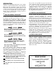
Table of Contents Guardian Liquid-cooled 27 kW and 30 kW Generators INTRODUCTION ................................................IFC SAFETY RULES ....................................................2 Section 3 — OPERATION ................................12 3.1 Using a Standard “GTS” Transfer Switch............12 3.2 Control Console Components..............................13 Section 1 — GENERAL INFORMATION ............4 3.3 Manual Transfer and Startup ..............................14 1.
IMPORTANT SAFETY INSTRUCTIONS Guardian Liquid-cooled 27 kW and 30 kW Generators ! SAVE THESE INSTRUCTIONS – The manufacturer suggests that these rules for safe operation be copied and posted in potential hazard areas. Safety should be stressed to all operators, potential operators, and service and repair technicians for this equipment. ! SAVE THESE INSTRUCTIONS – This manual contains important instructions that should be followed during installation and maintenance of the generator and batteries.
IMPORTANT SAFETY INSTRUCTIONS Guardian Liquid-cooled 27 kW and 30 kW Generators • Inspect the generator regularly, and promptly repair or replace all worn, damaged or defective parts using only factory-approved parts. • Before performing any maintenance on the generator, disconnect its battery cables to prevent accidental start-up. Disconnect the cable from the battery post indicated by a NEGATIVE, NEG or (–) first. Reconnect that cable last. • Never use the generator or any of its parts as a step.
Section 1 - General Information Guardian Liquid-cooled 27 kW and 30 kW Generators 1.1 GENERATOR 1.3 This equipment is a liquid-cooled, engine-driven generator set. The generator is designed to supply electrical power that operates critical electrical loads during utility power failure. The unit has been factory-installed in a weather resistant, all metal enclosure and is intended for outdoor installation only.
Section 1 - General Information Guardian Liquid-cooled 27 kW and 30 kW Generators 1.6 GENERATOR FUEL SYSTEM Figure 1.4 - Low Oil Pressure Switch The unit has been factory tested and adjusted using a natural gas fuel system. If propane (LP) gas is necessary, contact an authorized service dealer. Fuel pressure for a natural gas set up should be five inches to 14 inches of water column (0.18 to 0.5 psi) at all load ranges.
Section 1 — General Information Guardian Liquid-cooled 27 kW and 30 kW Generators Figure 1.6 - Low Coolant Level Sensor 1.7.7 LOW BATTERY The engine control board continually monitors the battery voltage and turns on the low battery LED if the battery voltage falls below 11.0 VDC for one minute. Low battery voltage is a non-latching alarm, which will automatically clear if the battery voltage rises above 11.0 VDC.
Section 1 — General Information Guardian Liquid-cooled 27 kW and 30 kW Generators Fuel pressure for a natural gas set up should be five inches to 14 inches of water column (0.18 to 0.5 psi) at all load ranges. 1.10 SPECIFICATIONS 1.10.1 GENERATOR SPECIFICATIONS Single-phase Model Rated Max. Cont. AC Power Output (kW) Rated voltage (volts) No.
Section 2 — Installation Guardian Liquid-cooled 27 kW and 30 kW Generators 1.13 TORQUE SPECIFICATIONS Cylinder Head ............................................15 (+ 90° + 90°) ft.lb. Intake Manifold ................................................................13 ft.lb. Exhaust Manifold..............................................................13 ft.lb. 1.14 ENGINE OIL RECOMMENDATIONS The unit has been filled with 5W-20 engine oil at the factory.
Section 2 — Installation Guardian Liquid-cooled 27 kW and 30 kW Generators • NFPA No. 37, STATIONARY COMBUSTION ENGINES AND GAS TURBINES. • NFPA No. 76A, ESSENTIAL ELECTRICAL SYSTEMS FOR HEALTH CARE FACILITIES. • NFPA No. 220, STANDARD TYPES OF BUILDING CONSTRUCTION • NFPA No. 68, GUIDE FOR EXPLOSION VENTING • NFPA No. 70, NATIONAL ELECTRICAL CODE. • NFPA No. 30, FLAMMABLE AND COMBUSTIBLE LIQUIDS CODE. • NFPA No. 10, INSTALLATION, MAINTENANCE AND USE OF PORTABLE FIRE EXTINGUISHERS.
Section 2 — Installation Guardian Liquid-cooled 27 kW and 30 kW Generators 2.5 EMERGENCY CIRCUIT ISOLATION METHOD Figure 2.2 – Generator Grounding Lug (typical) This prevents overloading the generator by keeping electrical loads below the wattage/amperage capacity of the generator. If the generator is powering only critical loads, within the wattage/amperage capacity, during utility power outages, consider using the emergency circuit isolation method.
Section 2 — Installation Guardian Liquid-cooled 27 kW and 30 kW Generators Control system interconnections consist of N1 and N2, and leads 23 and 194. Control system interconnection leads must be run in a conduit that is separate from the AC power lead. Recommended wire gauge sizes for this wiring depends on the length of the wire, as recommended below: MAXIMUM WIRE LENGTH 460 feet (140m) 461 to 730 feet (223m) 731 to 1,160 feet (354m) 1,161 to 1,850 feet (565m) 2.9.2 RECOMMENDED WIRE SIZE No. 18 AWG.
Section 3 — Operation Guardian Liquid-cooled 27 kW and 30 kW Generators 2.11.1 PRIOR TO INITIAL START-UP Prior to initially starting the generator, it must be properly prepared for use. Any attempt to crank or start the engine before it has been properly serviced with the recommended types and quantities of engine fluids (oil, coolant, fuel, etc.) may result in an engine failure. Before starting the generator for the first time, the installer must complete the following procedures.
Section 3 - Operation Guardian Liquid-cooled 27 kW and 30 kW Generators AUTO — The control board will monitor the two-wire start circuit. When a two-wire start is issued the control board will immediately start and run the generator. Whe the two-wire start is removed the control board will immediately stop the generator.
Section 3 — Operation Guardian Liquid-cooled 27 kW and 30 kW Generators 3.3 MANUAL TRANSFER AND START-UP To transfer electrical loads to the Standby (EMERGENCY) power source side and start the engine manually, refer to the Owner’s Manual of the particular transfer switch. 3.4 ENGINE GOVERNOR ADJUSTMENTS Engine speed governing is also controlled by the engine control board. Connector J2 on the engine control board interfaces with a governor driver module and the Bosch throttle body.
Section 4 — Maintenance Guardian Liquid-cooled 27 kW and 30 kW Generators 2. Press and hold the “Set Exercise” switch for three seconds, then release. At this time all five red LEDs will flash for approximately 10 seconds, then the engine will start and run for it’s 12 minute exercise period, then shut down. The generator will now start and run each week at the same time. C. ONCE ANNUALLY If DC power to the control board is lost, the weekly exercise setting will be lost.
Section 4 — Maintenance Guardian Liquid-cooled 27 kW and 30 kW Generators 4.4 CHECKING FLUID LEVELS 4.4.1 CHECK ENGINE OIL Check engine crankcase oil level (Figure 4.1) at least every 20 hours of operation, or prior to use. • Remove oil dipstick and wipe dry with a clean, lint-free cloth. • Install oil dipstick, then remove again. • Oil should be between FULL and ADD marks. • If oil level is below the dipstick ADD mark, remove oil fill cap.
Section 4 — Maintenance Guardian Liquid-cooled 27 kW and 30 kW Generators DANGER ! Do not attempt to adjust the governor. Only qualified service facilities should adjust the governor. Excessively high operating speeds are dangerous and increase the risk of personal injury. Low speeds impose a heavy load on the engine when adequate engine power is not available and may shorten engine life. Correct rated frequency and voltage are supplied only at the proper governed speed.
Section 4 — Maintenance Guardian Liquid-cooled 27 kW and 30 kW Generators Figure 4.4 – Setting the Spark Plug Gap SET PLUG GAP AT 1.06-1.16 mm (0.042-0.046 inch) 4.5.13 COOLANT CHANGE Every year, have Authorized Service Facility drain, flush and refill the cooling system. See SPECIFICATIONS (Section 1.10) for cooling system recommendations. 4.6 MISCELLANEOUS MAINTENANCE 4.6.1 CLEANING THE GENERATOR Keep the generator as clean and as dry as possible.
Section 4 — Maintenance Guardian Liquid-cooled 27 kW and 30 kW Generators ! ! Do not use any jumper cables or booster battery to crank and start the generator engine. If the battery has completely discharged, remove it from the generator for recharging. PERIODIC REPLACEMENT PARTS Part Name Oil Filter Radiator Cap Air Cleaner Spark Plug Generac’s Part Number # 0E7180 # 046627 # 0C8127 # 0E7079 Be sure the AUTO/OFF/MANUAL switch is set to the OFF position before connecting the battery cables.
Section 4 — Maintenance Guardian Liquid-cooled 27 kW and 30 kW Generators 4.7 SCHEDULED MAINTENANCE Following is a recommended maintenance schedule for Generac small standby and residential generator sets. The established intervals in the schedule are the maximum recommended when the unit is used in an average service application. They will need to be decreased (performed more frequently) if the unit is used in a severe application.
Section 4 — Maintenance Guardian Liquid-cooled 27 kW and 30 kW Generators Maintenance Tasks Level 1 Recommended to be done monthly/ 10 hrs. Level 2 Task Comp. (DateInitials) Required to be done 3 months/ Break-in 30 hrs. Level 3 Task Comp. (DateInitials) Required to be done Semiannually/ 50 hrs. Level 4 Task Comp. (DateInitials) Required to be done Annually/ 100 hrs. Task Comp. (DateInitials) 1. Disable the unit from operating per the first page warning. 2. Check the engine oil level.
Section 4 — Maintenance Guardian Liquid-cooled 27 kW and 30 kW Generators Maintenance Tasks Level 1 Recommended to be done monthly/ 10 hrs. 13. Initiate an automatic start and transfer of the unit to site load and exercise it for at least 1 hour looking for leaks, loose connections or components, and abnormal operating conditions. Correct as necessary. 14.
Section 5 — Troubleshooting Guardian Liquid-cooled 27 kW and 30 kW Generators TROUBLESHOOTING POINTS PROBLEM CAUSE CORRECTION Engine won’t crank. 1. 15 amp fuse blown. 2. Loose or corroded or defective battery cables. 3. Defective starter contactor. 4. Defective starter motor. 5. Dead or Defective Battery. 6. 4 amp fuse blown. 1. Replace fuse. 2. Tighten, clean or replace battery cables as necessary. 3. Replace contactor. 4. Replace starter motor. 5. Remove, change or replace battery. 6. Replace fuse.
Section 6 - Notes Guardian Liquid-cooled 27 kW and 30 kW Generators 24 Generac® Power Systems, Inc.
Section 7 — Installation Diagram Guardian Liquid-cooled 27 kW and 30 kW Generators Installation Diagram — Drawing No. 0E8695 Generac® Power Systems, Inc.
Section 8 - Electrical Data Guardian Liquid-cooled 27 kW and 30 kW Generators Wiring Diagram — Engine — Drawing No.
Section 8 - Electrical Data Guardian Liquid-cooled 27 kW and 30 kW Generators Wiring Diagram — Engine — Drawing No.
Section 8 - Electrical Data Guardian Liquid-cooled 27 kW and 30 kW Generators Electrical Schematic — Engine — Drawing No. 0E6200-B ALTERNATOR ROTOR ALTERNATOR STATOR AUTOMATIC VOLTAGE REGULATOR BRUSH ASSEMLY (GENERATOR) BATTERY CHARGER BATTERY CHARGE WINDING CIRCUIT BREAKER (OUTPUT) CIRCUIT BREAKER (EXCITATION) DIODE [FIELD BOOST] DISPLACED PHASE EXCITATION LEGEND {CONT.]: F1 FUSE, BAT. POWER (15A AGC TYPE) F2 FUSE, B/C (4A AGC TYPE) ICT TERMINAL BLOCK, INTERCONNECT.
Section 8 - Electrical Data Guardian Liquid-cooled 27 kW and 30 kW Generators Electrical Schematic — Engine — Drawing No.
16 30 Generac® Power Systems, Inc. 7 6 5 2 4 3 ENGINE FOOT 12 13 17 9 35 18 16 8 40 3 36 30 16 43 44 TO ENGINE BLOCK 34 35 41 38 18 44 32 33 22 42 20 31 20 7 6 5 37 15 1 13 14 12 11 REAR BEARING CARRIER HARNESS WIRE TO STARTER CONTACTOR TO STARTER BOLT TO ENGINE 18 BLOCK 14 16 10 4 3 2 Section 9 - Exploded Views and Parts Guardian Liquid-cooled 27 kW and 30 kW Generators Mounting Base — Drawing No.
Section 9 - Exploded Views and Parts Guardian Liquid-cooled 27 kW and 30 kW Generators Mounting Base — Drawing No. 0E6266-E ITEM 1 2 3 4 5 6 7 8 9 10 11 12 13 14 15 16 17 18 20 21 22 23 * 24 * 25 * 26 * 30 31 32 33 34 35 36 37 38 39 40 41 42 43 44 PART NO.
32 Generac® Power Systems, Inc. 3 30 31 LATCH DETAIL 38 32 4 34 18 17 43 27 2 41 4 37 35 25 RADIATOR SUPPORT 53 4 33 4 STATES FOAM IS ON FAR SIDE STATES FOAM IS ON NEAR SIDE 5555 53 44 4 4 4 13 11 9 SEE LATCH DETAIL 26 5588 TO "A" TYPICAL OF ROOF PANEL THAT REQUIRE INSULATION. SECURE AS SHOWN.
Section 9 - Exploded Views and Parts Guardian Liquid-cooled 27 kW and 30 kW Generators Compartment — Drawing No. 0E8333-D ITEM 1 2 3 4 5 6 7 8 9 10 11 12 13 14 15 16 17 18 19 20 21 22 23 24 25 26 27 28 29 30 31 32 33 34 35 36 37 38 39 40 41 42 43 44 50 * 51 52 53 54 55 56 57 58 59 PART NO.
Section 9 - Exploded Views and Parts Guardian Liquid-cooled 27 kW and 30 kW Generators Control Panel — Drawing No. 0E7118-K 34 Generac® Power Systems, Inc.
Section 9 - Exploded Views and Parts Guardian Liquid-cooled 27 kW and 30 kW Generators Control Panel — Drawing No. 0E7118-K ITEM PART NO. QTY. 1 2 3 4 5 6 7 8 9 10 11 12 13 14 15 16 17 18 19 20 21 0E7195 0E7196 0E7197 0E7193 0E7194 0E4494 082573 032300 022676 067682B 060015 054199 0C2657 099076 040213 0E9668 067680 0E6875A 0E6881 * 0C5139 * 0C5142 * 1 1 1 1 1 1 1 2 1 1 1 1 1 1 2 1 1 1 REF. REF. REF.
Section 9 - Exploded Views and Parts Guardian Liquid-cooled 27 kW and 30 kW Generators Engine — Drawing No. 0E8170-N 69 27 28 57 58 1 14 60 24 84 15 25 42 85 2 38 55 42 33 7 51 47 42 4 36 35 34 8 37 6 12 5 BAFFLE REAR UPPER 42 49 82 40 81 78 35 36 81 42 49 86 36 3 43 38 10 8 6 2 11 47 46 47 26 73 29 2 57 58 30 60 48 44 30 61 24 36 35 39 25 32 64 48 17 39 63 68 31 45 35 42 65 GROUND WIRE 66 36 Generac® Power Systems, Inc.
Section 9 - Exploded Views and Parts Guardian Liquid-cooled 27 kW and 30 kW Generators Engine — Drawing No. 0E8170-N ITEM PART NO. QTY.
Section 9 - Exploded Views and Parts 15 FRAME 9 8 3 38 Generac® Power Systems, Inc. 11 10 9 12 "A" 27 20 15 1 4 21 3 12 TO WATER PUMP 24 22 24 2 6 17 7 12 TO ENGINE 5 13 12 18 14 TO "A" Guardian Liquid-cooled 27 kW and 30 kW Generators Radiator — Drawing No.
Section 9 - Exploded Views and Parts Guardian Liquid-cooled 27 kW and 30 kW Generators Radiator — Drawing No. 0E8528-B ITEM 1 2 3 4 5 6 7 8 9 10 11 12 13 14 15 17 18 20 21 22 23 24 25 26 27 PART NO. 0E9947 0E6340 0E8531 0E6398 0E6397 080713 076749 049814 022131 046526 045772 035685 0E8562 058443 0C2454 048031C 029032 046627 069811 065852 0A2111 052250 035461 0C7649 069860C QTY. 1 1 2 1 1 1 1 4 8 4 4 4 1 4 9 1 1 1 1 1 1 2 1 1 1 DESCRIPTION RADIATOR R-IN,L-OUT 658X489X49 VENTURI 3.
Section 9 - Exploded Views and Parts 41 15 "B" 28 21 40 Generac® Power Systems, Inc. 5 16 2 4 10 29 32 30 29 11 17 6 1 7 9 31 29 6 8 3 3 33 14 TO "B" 18 26 27 28 26 40 43 39 Guardian Liquid-cooled 27 kW and 30 kW Generators Fuel System — Drawing No.
Section 9 - Exploded Views and Parts Guardian Liquid-cooled 27 kW and 30 kW Generators Fuel System — Drawing No. 0E8190-C ITEM PART NO.
Section 9 - Exploded Views and Parts 12 8 7 5 18 42 Generac® Power Systems, Inc. LOCKTIGHT 15 7 17 1 4 16 31 30 LEADS 2 6 9 21 13 LOCKTIGHT 3 10 11 20 19 14 Guardian Liquid-cooled 27 kW and 30 kW Generators Alternator — Drawing No.
Section 9 - Exploded Views and Parts Guardian Liquid-cooled 27 kW and 30 kW Generators Alternator — Drawing No. 0F5092-A ITEM PART NO. QTY.
Section 9 - Exploded Views and Parts Guardian Liquid-cooled 27 kW and 30 kW Generators Muffler — Drawing No. 0E6479-E 9 13 5 13 7 10 11 13 12 6 10 11 TO COMPARTMENT 13 12 22 2 TO MANIFOLD 11 17 8 1 21 4 8 8 19 2 TO MANIFOLD 8 20 17 3 18 21 19 20 18 ITEM 1 2 3 4 5 6 7 8 9 10 PART NO. QTY. 0E6134 0E6464 0E6465 0E6465A 0E5914 1 2 1 1 1 060366 027837 036797 039253 022145 1 1 4 2 2 DESCRIPTION MUFFLER, 3.0L FORD EXHAUST ELBOW 3.0L FORD HSB EXHAUST PIPE LH 3.
Section 9 - Exploded Views and Parts Guardian Liquid-cooled 27 kW and 30 kW Generators Air Cleaner — Drawing No. 0E8189-A ITEM PART NO. QTY. 1 2 3 4 5 0E5193 0E8200 0E8201 036434 0E0519A 1 1 1 1 1 6 7 8 9 10 0C8127 0A5547 062974 022127 037561 1 1 1 1 1 DESCRIPTION PLATE AIR CLEANER ADAPTER TUBE AIR INTAKE 3.0L FORD BRACKET AIR INTAKE 3.0L FORD BOLT U 5/16-18 X 2.
Section 10 – Warranty Guardian Liquid-cooled 27 kW and 30 kW Generators GENERAC POWER SYSTEMS "TWO YEAR" LIMITED WARRANTY FOR GUARDIAN® "PREPACKAGED EMERGENCY AUTOMATIC STANDBY GENERATORS" For a period of two years from the date of original sale, Generac Power Systems, Inc. (Generac) warrants that its Guardian generator will be free from defects in material and workmanship for the items and period set forth below.