Owner’s Manual Liquid-cooled, Prepackaged Standby Generators Model Nos. 005040-0, 005040-1 (25kW) 005053-0, 005053-1 (20kW) 005054-0, 005054-1 (15kW) This manual should remain with the unit.
INTRODUCTION Thank you for purchasing this model of the Guardian Elite standby generator series by Generac Power Systems, Inc.. Every effort was expended to make sure that the information and instructions in this manual are both accurate and current at the time the manual was written. However, the manufacturer reserves the right to change, alter or otherwise improve this product(s) at any time without prior notice.
Table of Contents Guardian Liquid-cooled 25 kW Generator INTRODUCTION ................................................IFC Section 3 — OPERATION ................................12 Read this Manual Thoroughly......................................IFC 3.1 Engineered GTS Transfer Switch ........................12 Operation and Maintenance ........................................IFC 3.2 Control Console Components..............................13 How to Obtain Service ......................................
Important Safety Instructions Guardian Liquid-cooled 25 kW Generator ! SAVE THESE INSTRUCTIONS – The manufacturer suggests that these rules for safe operation be copied and posted in potential hazard areas. Safety should be stressed to all operators, potential operators, and service and repair technicians for this equipment. ! SAVE THESE INSTRUCTIONS – This manual contains important instructions that should be followed during installation and maintenance of the generator and batteries.
Important Safety Instructions Guardian Liquid-cooled 25 kW Generator ELECTRICAL HAZARDS FIRE HAZARDS • All generators covered by this manual produce dangerous electrical voltages and can cause fatal electrical shock. Utility power delivers extremely high and dangerous voltages to the transfer switch as well as the standby generator. Avoid contact with bare wires, terminals, connections, etc., on the generator as well as the transfer switch, if applicable.
Section 1 - General Information Guardian Liquid-cooled 25 kW Generator 1.1 GENERATOR This equipment is a liquid-cooled, engine-driven generator set. The generator is designed to supply electrical power that operates critical electrical loads during utility power failure. The unit has been factory-installed in a weather resistant, all metal enclosure and is intended for outdoor installation only. Use this generator as a source of electrical power for the operation of 120 and/or 240VAC, single-phase loads.
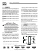
Section 1 - General Information Guardian Liquid-cooled 25 kW Generator 1.5 MAIN CIRCUIT BREAKER The generator’s main circuit breaker is included with the unit as shipped from the factory. The breaker for each unit is described in Figure 1.2. 1.6 GENERATOR FUEL SYSTEM This unit has been factory tested and adjusted using a natural gas fuel system. If propane (LP) gas is preferred, refer to Section 1.12, Reconfiguring the Fuel System for LP Vapor. 1.7.
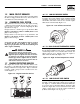
Section 1 — General Information Guardian Liquid-cooled 25 kW Generator Figure 1.6 - Low Coolant Level Sensor 1.8.2 INSPECTION Upon delivery, carefully inspect the generator for any damage that may have occurred during shipment. If loss or damage is noted at the time of delivery, have the person(s) making delivery note all damage on the freight bill or affix their signature under the consignor’s memo of loss or damage. 1.9 1.7.
Section 1 — General Information Guardian Liquid-cooled 25 kW Generator 1.10.2 GENERATOR Model Rated Max. Cont. AC Power Output (kW) Rated voltage (volts) No.
Section 2 — Installation Guardian Liquid-cooled 25 kW Generator 1.13 ENGINE OIL RECOMMENDATIONS The unit has been filled with 15W-40 engine oil at the factory. Use a high-quality detergent oil classified “For Service CC, SD, SE, SF.” Detergent oils keep the engine cleaner and reduce carbon deposits.
Section 2 — Installation Guardian Liquid-cooled 25 kW Generator • NFPA No. 68, GUIDE FOR EXPLOSION VENTING • NFPA No. 70, NATIONAL ELECTRICAL CODE. • NFPA No. 30, FLAMMABLE AND COMBUSTIBLE LIQUIDS CODE. • NFPA No. 10, INSTALLATION, MAINTENANCE AND USE OF PORTABLE FIRE EXTINGUISHERS. 2.1.
Section 2 — Installation Guardian Liquid-cooled 25 kW Generator 2.5 EMERGENCY CIRCUIT ISOLATION METHOD Figure 2.2 – Generator Grounding Lug (typical) This prevents overloading the generator by keeping electrical loads below the wattage/amperage capacity of the generator. If the generator is powering only critical loads, within the wattage/amperage capacity, during utility power outages, consider using the emergency circuit isolation method.
Section 2 — Installation Guardian Liquid-cooled 25 kW Generator Pos2 OFF — Standard Prepackaged ATS Application • The control board will perform all of the automatic features listed in this document. • The two-wire start connections, wires 178-183, should NOT be connected. NOTE: If the generator is installed in conjunction with an engineered GTS type transfer switch, refer to the applicable transfer switch manual for exact operating parameters and timing sequences. 2.
Section 3 - Operation Guardian Liquid-cooled 25 kW Generator 2.11 PREPARATION BEFORE START-UP 2.11.5 ENGINE COOLANT The instructions in this section assume that the standby generator has been properly installed, serviced, tested, adjusted and otherwise prepared for use by a competent, qualified installation contractor. Be sure to read the “Safety Rules” on pages 2 and 3, as well as all other safety information in this manual, before attempting to operate this (and related) equipment.
Section 3 - Operation Guardian Liquid-cooled 25 kW Generator GTS Mode Operation When in GTS mode, the control board will respond as follows based on the generator AUTO/OFF/MANUAL switch position. OFF — The generator will not start and run in this position. MANUAL — The control board will start and run the generator whenever the switch is in the manual position. AUTO — The control board will monitor the two-wire start circuit.
Section 3 - Operation Guardian Liquid-cooled 25 kW Generator Condition System Ready (Green) Low Bat (Red) Low Oil (Red) High Temp (Red) Over Speed (Red) Over Crank (Red) Generator Switch is in the OFF Mode.
Section 3 - Operation Guardian Liquid-cooled 25 kW Generator 3. Under no load condition, increase the GAIN pot as much as possible without causing instability. 4. Apply 1/4, 1/2, 3/4 and full load to the unit. Decrease the GAIN pot if there is instability at any load point. 5. Under full load condition, increase the stability pot until the unit returns to 60 Hertz (or 50 Hertz in 50 Hertz applications). 6. Reduce load to 3/4, 1/2, 1/4 and no load.
Section 4 — Maintenance Guardian Liquid-cooled 25 kW Generator At this time all five red LEDs will flash for approximately 10 seconds, then the engine will start and run for it’s 12 minute exercise period, then shut down. The generator will now start and run each week at the same time. If DC power to the control board is lost, the weekly exercise setting will be lost. This is indicated by all five red LEDs continually flashing.
Section 4 — Maintenance Guardian Liquid-cooled 25 kW Generator F. EVERY 800 OPERATING HOURS 4.4 1. Retorque cylinder head (see torque specs). 2. Retorque intake and exhaust manifold (see torque specs). 3. Check engine compression. 4. Check valve clearance. 1. Position head gasket on the block (Figure 4.2). 2. Position cylinder head to cylinder block. 3. Install 10 cylinder head bolts in numerical sequence. Tighten to 70 N-m (52 lb-ft) in sequence. Retighten to 70 N-m (52 lb-ft) in sequence.
Section 4 — Maintenance Guardian Liquid-cooled 25 kW Generator 4.6 OVERLOAD PROTECTION FOR ENGINE DC ELECTRICAL SYSTEM Engine cranking, start up and running are controlled by a solid state Engine Controller circuit board. Battery voltage is delivered to that circuit board via a 15 amp fuse. These overcurrent protection devices will open if the circuit is overloaded. ! 4.
Section 4 — Maintenance Guardian Liquid-cooled 25 kW Generator 4.8.8 CHECK FAN BELT • Inspect fan belts every three months. Replace any damaged, deteriorated, worn or otherwise defective belt. • Check fan belt tension. Thumb pressure, exerted midway between pulleys, should deflect about 3/8 to 5/8 of an inch. Adjust belt tension as required. 4.8.9 INSPECT ENGINE GOVERNOR Visually inspect electronic governor. DANGER ! DANGER: Do not attempt to adjust the governor.
Section 4 — Maintenance Guardian Liquid-cooled 25 kW Generator 4.9 MISCELLANEOUS MAINTENANCE 4.9.1 CLEANING THE GENERATOR Keep the generator as clean and as dry as possible. Dirt and moisture that accumulates on internal generator windings have an adverse effect on insulation resistance. 2. Check the battery fluid level of unsealed batteries and, if necessary, fill with DISTILLED WATER ONLY. DO NOT USE TAP WATER IN BATTERIES. 3. Have the state of charge and condition checked.
Section 4 — Maintenance Guardian Liquid-cooled 25 kW Generator 4.10 SCHEDULED MAINTENANCE Following is a recommended maintenance schedule for Generac small standby and residential generator sets. The established intervals in the schedule are the maximum recommended when the unit is used in an average service application. They will need to be decreased (performed more frequently) if the unit is used in a severe application.
Section 4 — Maintenance Guardian Liquid-cooled 25 kW Generator Maintenance Tasks Level 1 Recommended to be done monthly 1. Disable the unit from operating per the first page warning. 2. Check the engine oil level. Adjust as necessary. 3. Check the engine coolant level. Adjust as necessary. 4. Check the engine coolant thermal protection level. Correct as necessary. 5. Check the natural gas delivery system on gas engine driven units. Tighten connections as necessary. 6.
Section 4 — Maintenance Guardian Liquid-cooled 25 kW Generator Maintenance Tasks Level 1 Recommended to be done monthly Level 2 Task Comp. (DateInitials) Required to be done 3 months/ Break-in Level 3 Task Comp. (DateInitials) Required to be done Semiannually Level 4 Task Comp. (DateInitials) Required to be done Annually Task Comp. (DateInitials) 13.
Section 5 — Troubleshooting Guardian Liquid-cooled 25 kW Generator TROUBLESHOOTING POINTS PROBLEM CAUSE CORRECTION Engine won’t crank. 1. 15 amp fuse blown. 2. Loose or corroded or defective battery cables. 3. Defective starter contactor. 4. Defective starter motor. 5. Dead or Defective Battery. 6. 5 amp fuse blown. 1. Replace fuse. 2. Tighten, clean or replace battery cables as necessary. 3. Replace contactor. 4. Replace starter motor. 5. Remove, change or replace battery. 6. Replace fuse.
Section 6 — Notes Guardian Liquid-cooled 25 kW Generator Generac® Power Systems, Inc.
Section 7 - Electrical Data Guardian Liquid-cooled 25 kW Generator Wiring Diagram — 2.5L Engine (15kW & 20kW units) —Drawing No. 0F1411 26 Generac® Power Systems, Inc.
Section 7 - Electrical Data Guardian Liquid-cooled 25 kW Generator Wiring Diagram — 2.5L Engine (15kW & 20kW units) —Drawing No. 0F1411 Generac® Power Systems, Inc.
Section 7 - Electrical Data Guardian Liquid-cooled 25 kW Generator Electrical Schematic — 2.5L Engine (15kW & 20kW units) —Drawing No. 0F1413 28 Generac® Power Systems, Inc.
Section 7 - Electrical Data Guardian Liquid-cooled 25 kW Generator Electrical Schematic — 2.5L Engine (15kW & 20kW units) —Drawing No. 0F1413 Generac® Power Systems, Inc.
Section 7 - Electrical Data Guardian Liquid-cooled 25 kW Generator Wiring Diagram — 2.5L Engine (25kW unit) —Drawing No. 0E9982-B 30 Generac® Power Systems, Inc.
Section 7 - Electrical Data Guardian Liquid-cooled 25 kW Generator Wiring Diagram — 2.5L Engine (25kW unit) —Drawing No. 0E9982-B Generac® Power Systems, Inc.
Section 7 - Electrical Data Guardian Liquid-cooled 25 kW Generator Electrical Schematic — 2.5L (25kW unit) — Drawing No. 0E9983-B 32 Generac® Power Systems, Inc.
Section 7 - Electrical Data Guardian Liquid-cooled 25 kW Generator Electrical Schematic — 2.5L (25kW unit) — Drawing No. 0E9983-B Generac® Power Systems, Inc.
34 Generac® Power Systems, Inc. 3 2 PANEL BOTTOM 3 15 14 13 12 11 1 4 5 35 3 1 10 36 10 REAR BEARING CARRIER 15 14 13 12 11 3 2 6 8 3 9 21 22 27 23 1 26 33 20 25 24 34 3 29 28 3 30 29 6 TO STARTER BOLT TO ENGINE BLOCK 19 17 32 2 O MOUNT 16 HARNESS WIRE TO STARTER Section 8 - Exploded Views and Parts Guardian Liquid-cooled 25 kW Generator Mounting Base — Drawing No.
Section 8 - Exploded Views and Parts Guardian Liquid-cooled 25 kW Generator Mounting Base — Drawing No. 0E9964-E ITEM 1 2 3 4 5 6 7 8 9 10 11 12 13 14 15 16 17 18 19 20 21 22 23 24 25 26 27 28 29 30 31 32 33 34 35 36 PART NO. 0D9336 0E9939 0C2454 049813 022097 026850 055414 022473 047411 052860 052251 052257 052252 052259 052891 0536210261 074906 077483 0E9941 025507 059980 046526 022131 021991 038805J 050331 050331A 038804J 045771 022129 027482 075763 0E9748 0E9940 065852 024469 QTY.
Section 8 - Exploded Views and Parts Guardian Liquid-cooled 25 kW Generator Enclosure — Drawing No. 0E9720-D WELD STUD UNDER ROOF PANEL FOR ACCESS COVER CABLE 21 13 14 2 29 4 36 1 15 11 41 16 11 "Y" 26 10 10 2 37 3 34 40 26 "Y" 22 23 20 17 18 19 11 4 3 35 35 3 33 2 29 11 9 15 8 26 15 24 6 25 2 26 11 17 10 19 18 30 24 19 17 10 25 32 38 5 31 7 11 36 Generac® Power Systems, Inc. 3 NOTE: USE DOOR LATCH FASTENER TO SECURE GROUND WIRE. NOTE: USE LOCTITE ON NUTS ITEM #26.
Section 8 - Exploded Views and Parts Guardian Liquid-cooled 25 kW Generator Enclosure — Drawing No. 0E9720-D ITEM 1 2 3 4 5 6 7 8 9 10 11 12 13 14 15 16 17 18 19 20 21 22 23 24 25 26 27 28 29 30 31 32 33 34 35 36 37 38 39 40 41 PART NO.
Section 8 - Exploded Views and Parts 14 11 37 65 30 54 52 50 41 33 44 32 15 1 5 19 40 14 14 4 10 1 14 26 2 13 TO "A" 48 4 3 27 7 24 9 36 35 34 21 35 43 34 "A" 31 33 29 22 34 17 3 23 16 0 5 56 12 35 34 36 35 6 54 64 18 38 39 Guardian Liquid-cooled 25 kW Generator Control Panel — Drawing No. 0E9719-E 38 Generac® Power Systems, Inc.
Section 8 - Exploded Views and Parts Guardian Liquid-cooled 25 kW Generator Control Panel — Drawing No. 0E9719-E ITEM PART NO. QTY.
Section 8 - Exploded Views and Parts Guardian Liquid-cooled 25 kW Generator Control Panel — Drawing No. 0F1378-D 40 Generac® Power Systems, Inc.
Section 8 - Exploded Views and Parts Guardian Liquid-cooled 25 kW Generator Control Panel — Drawing No. 0F1378-D ITEM PART NO. QTY.
30 42 Generac® Power Systems, Inc. 41 20 30 19 20 29 27 60 20 39 59 28 38 19 14 39 16 52 40 25 38 4 10 2 17 15 22 5 19 45 19 3 0 3 34 3 68 19 20 47 FOR HARNESS GROUND 20 HSG. 4 46 17 22 15 1 48 50 35 49 39 16 65 33 15 51 67 20 18 "A" 61 "A" 18 62 17 58 18 38 TO RADIATOR CAP 39 23 STEPPER MOTOR UNITS ONLY Section 8 - Exploded Views and Parts Guardian Liquid-cooled 25 kW Generator Engine — Drawing No.
Section 8 - Exploded Views and Parts Guardian Liquid-cooled 25 kW Generator Engine — Drawing No. 0E9918-E ITEM PART NO. QTY. DESCRIPTION 1 2 3 4 5 6 7 0E9909 0E9739 049814 0F0001 0D3488B 0A8584 0E0561 REF 1 8 1 1 1 1 ENGINE 2.5L FORD PULLEY, 2.5L FORD WATER PUMP SCREW HHC M10-1.5 X 25 G8.8 CLUTCH, COOLING FAN 2.
44 Generac® Power Systems, Inc. 12 TO VALVE 1 COVER 17 20 28 TO ENGINE 10 32 31 8 33 18 42 30 6 26 7 35 22 21 38 34 16 24 25 13 9 41 PORT "OUT 2" 3 11 4 15 29 CARBURETOR ASSY. 0E1028A (I/N 19) L.P. VAPOR CONVERSION 40 5 27 1 4 6 3 40 11 2 PORT "OUT 1" 6 7 Section 8 - Exploded Views and Parts Guardian Liquid-cooled 25 kW Generator Fuel System — Drawing No.
Section 8 - Exploded Views and Parts Guardian Liquid-cooled 25 kW Generator Fuel System — Drawing No. 0E9980-D ITEM 1 2 3 4 5 6 7 8* 9 10 11 12 13 14 15 16 * 17 18 19 20 21 * 22 * 23 24 25 26 27 28 29 30* 31* 32* 33* 34* 35* 36* 37* 38* 39* 40 41 42 PART NO.
Section 8 - Exploded Views and Parts 12 8 7 5 18 46 Generac® Power Systems, Inc. LOCKTIGHT 15 7 17 1 4 16 31 30 LEADS 2 6 9 21 13* LOCKTIGHT 3 10 11 20 19 14 Guardian Liquid-cooled 25 kW Generator Alternator — Drawing No.
Section 8 - Exploded Views and Parts Guardian Liquid-cooled 25 kW Generator Alternator — Drawing No. 0E8660-C ITEM PART NO. QTY.
Section 8 - Exploded Views and Parts Guardian Liquid-cooled 25 kW Generator Muffler — Drawing No. 0F2930-B 1 5 4 24 6 7 11 3 17 19 20 13 15 20 12 11 20 5 7 4 6 18 6 15 14 16 9 8 10 2 21 22 23 ITEM 1 2 3 4 5 6 7 8 9 10 11 12 PART NO. 0F2912 0F2869 0F2823 036434 036449 022129 022259 0E0170A 044149 0E8816 0F2925 0F2926 QTY. 1 1 1 2 2 6 4 1 1 1 2 1 DESCRIPTION PIPE MUFFLER OUT PIPE EXHAUST 2.5L FORD MUFFLER 2.5L FORD BOLT U 5/16-18 X 2.
Section 8 - Exploded Views and Parts Guardian Liquid-cooled 25 kW Generator Stepper Motor — Drawing No. 0E9979-C 5 4 3 ITEM (13) NEOPRENE COATING 2 1 14 6 7 10 WIRE HARNESS 15 12 9 "A" 10 7 CARBURETOR ARM (REF.) 6 SECURE WIRE HARNESS WITH TIE WRAP AS SHOWN. 7 16 17 TO "A" INTAKE MANIFOLD (REF.) 11 ITEM 1 2 3 4 5 6 7 8 9 10 11 12 13 14 15 16 17 18 PART NO. 098290 098941A 0F0454 098942A 098225 043146 022097 0E7358 098783 037398 0E1326 0A7106 074031 029333A 022507 022473 064526 0E1694 QTY.
Section 8 - Exploded Views and Parts Guardian Liquid-cooled 25 kW Generator Radiator — Drawing No. 0E9965-D 1 19 18 12 5 11 2 18 14 8 10 TO BASE OF WATER INLET 7 25 5 9 7 24 15 3 16 4 17 6 9 10 ITEM 1 2 3 4 5 6 7 8 9 10 11 12 PART NO. 0E9769 0F0779 0E9837 0F0123 0F0118 099502 0C2454 052250 022097 022473 022127 046627 060035 QTY. REF REF 1 1 1 4 REF. 2 8 12 8 1 4 DESCRIPTION SUPPORT,RADIATOR 2.5L FORD SUPPORT RADIATOR 2.5L AL RADIATOR, 2.5L FORD VENTURI, 16" FAN 2.5L FORD GUARD, FAN 2.
Section 9 — Installation Diagram Guardian Liquid-cooled 25 kW Generator Installation Diagram — Drawing No. 0F1020-A Generac® Power Systems, Inc.
Section 10 – Warranty Guardian Liquid-cooled 25 kW Generator CALIFORNIA EMISSION CONTROL WARRANTY STATEMENT YOUR WARRANTY RIGHTS AND OBLIGATIONS The California Air Resources Board (CARB) and Generac Power Systems, Inc. (Generac) are pleased to explain the Emission Control System Warranty on your new engine.* In California, new utility, and lawn and garden equipment engines must be designed, built and equipped to meet the state’s stringent anti-smog standards.
Section 10 – Warranty Guardian Liquid-cooled 25 kW Generator EMISSION CONTROL SYSTEM WARRANTY Emission Control System Warranty (ECS Warranty) for 1995 and later model year engines: (a) Applicability: This warranty shall apply to 1995 and later model year engines. The ECS Warranty Period shall begin on the date the new engine or equipment is purchased by/delivered to its original, end-use purchaser/owner and shall continue for 24 consecutive months thereafter.
Section 10 – Warranty Guardian Liquid-cooled 25 kW Generator GENERAC POWER SYSTEMS "TWO YEAR" LIMITED WARRANTY FOR GUARDIAN® "PREPACKAGED EMERGENCY AUTOMATIC STANDBY GENERATORS" For a period of two years from the date of original sale, Generac Power Systems, Inc. (Generac) warrants that its Guardian generator will be free from defects in material and workmanship for the items and period set forth below.