2.4L 35kW Models: 005259-1 005260-1 Serial Number STANDBY GENERATOR OWNER'S MANUAL A new standard of reliability Not intended for use in critical life support applications. —CAUTION— ONLY QUALIFIED ELECTRICIANS OR CONTRACTORS SHOULD ATTEMPT INSTALLATION! DEADLY EXHAUST FUMES. OUTDOOR INSTALLATION ONLY! This manual should remain with the unit. Cover057 Rev. A 05/06 Part No.
Standby Generator Sets Table of Contents INTRODUCTION .....................................................1-3 Read this Manual Thoroughly ...................................1-3 Operation and Maintenance ......................................1-3 How to Obtain Service ..............................................1-3 IDENTIFICATION RECORD .....................................2-1 Data Label ................................................................2-1 EQUIPMENT DESCRIPTION .............................
Standby Generator Sets Important Safety Instructions WARNING: GENERAL HAZARDS • For safety reasons, the manufacturer recommends that this equipment be installed, serviced and repaired by an Authorized Service Dealer or other competent, qualified electrician or installation technician who is familiar with applicable codes, standards and regulations. The operator also must comply with all such codes, standards and regulations.
Standby Generator Sets Important Safety Instructions • Generators installed with an automatic transfer switch will crank and start automatically when normal (utility) source voltage is removed or is below an acceptable preset level. To prevent such automatic start-up and possible injury to personnel, disable the generator’s automatic start circuit (battery cables, etc.) before working on or around the unit. Then, place a “Do Not Operate” tag on the generator control panel and on the transfer switch.
Standby Generator Sets Important Safety Instructions INTRODUCTION This symbol points out potential fire hazard. symbol points out potential electrical shock This hazard. Thank you for purchasing this model of the standby generator set product line. Every effort was expended to make sure that the information and instructions in this manual were both accurate and current at the time the manual was written.
Standby Generator Sets General Information IDENTIFICATION RECORD NOTE: For actual information related to this particular model, please refer to the Manual Drawing Listing located at the end of this manual, or to the data label affixed to the unit. DATA LABEL Every generator set has a DATA LABEL that contains important information pertinent to the generator.
Standby Generator Sets Equipment Description EQUIPMENT DESCRIPTION COOLANT RECOMMENDATIONS This equipment is a revolving field, alternating current generator set. It is powered by a gaseous fueled engine operating at 1800 rpm for 4-pole direct drive units, 3600 rpm for 2-pole direct drive units and 2300 - 3000 rpm for quiet drive gear units. See the Specifications section for exact numbers.
Standby Generator Sets Engine Protective Devices ENGINE PROTECTIVE DEVICES OVERCRANK SHUTDOWN The standby generator may be required to operate for long periods of time without an operator on hand to monitor such engine conditions as coolant temperature, oil pressure or rpm.
Standby Generator Sets Fuel Systems FUEL SYSTEM PROPANE VAPOR WITHDRAWAL FUEL SYSTEM FUEL REQUIREMENTS This type of system utilizes the vapors formed above the liquid fuel in the supply tank. Approximately 10 to 20 percent of the tank capacity is needed for fuel expansion from the liquid to the vapor state. The vapor withdrawal system is generally best suited for smaller engines that require less fuel.
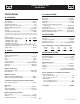
Standby Generator Sets Specifications SPECIFICATIONS COOLING SYSTEM GENERATOR Type ...................................................Pressurized Closed Recovery Water Pump.................................................................... Belt Driven Fan Speed .........................................................................2150 rpm Fan Diameter .....................................................................22 inches Fan Mode ..........................................................
Standby Generator Sets Specifications Figure 1 — Interconnections Utility In Transfer Switch CONTROL PANEL NEUTRAL TO ALTERNATOR Gen N1 N2 23 194 GENERATOR CONNECTION BOX 183 178 NEUTRAL N1 N2 23 194 4- # 14 GA WIRES TO GENERATOR CONNECTION BOX CIRCUIT BREAKER Battery Charger Input 186 178 Load Out TO GENERATOR CONNECTION BOX GROUND 120 Volt + Neutral Grd To Generator Control Panel FRAME RAIL Ground Level Concrete Slab KW 35 35 35 STUB-UP AREA See Install Dwg for Dimensions COLD WEA
Standby Generator Sets General Information GENERATOR AC LEAD CONNECTIONS ALTERNATOR POWER WINDING CONNECTIONS See “Voltage Codes”. This generator may be rated at any one of three voltages, either single-phase or three-phase. The electrical wires in the unit’s AC connection (lower) panel should be installed according to the number of leads and the voltage/phase required for the application. If there are any questions regarding lead connection, refer to the wiring diagrams at the back of this manual.
Standby Generator Sets Installation PRIOR TO INITIAL START-UP INSTALLATION Refer to the separate “Installation Guide QT Product Line” supplied with the unit. to initially starting the generator, it must Prior be properly prepared for use. Any attempt to PREPARATION BEFORE START-UP The instructions in this section assume that the standby generator has been properly installed, serviced, tested, adjusted and otherwise prepared for use by a competent, qualified installation contractor.
Standby Generator Sets Installation START-UP CHECKLIST • Check voltage at the generator terminals. • For 3-phase units, check phase rotation at the transfer switch terminals. The generator phase rotation must match the utility phase rotation. • Check for coolant, fuel, oil, and exhaust leaks. • Close the generators main line circuit breaker. • Turn the generator set off. • Connect the UTILITY supply to the transfer switch. • Set the AUTO/OFF/MANUAL switch to AUTO.
Standby Generator Sets Operation GENERATOR CONTROL AND OPERATION not crank the engine continuously for longer Do than 30 seconds, or the heat may Refer to the appropriate control panel operator’s manual for this unit. • • OPERATING UNIT WITH MANUAL TRANSFER SWITCH If the generator was installed in conjunction with a transfer switch capable of manual operation only, the following procedure applies.
Standby Generator Sets Maintenance MAINTENANCE PERFORMED BY AUTHORIZED SERVICE FACILITIES COOLING SYSTEM Air intake and outlet openings in the generator compartment must be open and unobstructed for continued proper operation. This includes such obstructions as high grass, weeds, brush, leaves and snow. working on the generator, ensure the fol Before lowing: Without sufficient cooling and ventilating air flow, the engine/generator quickly overheats, which causes it to shut down.
Standby Generator Sets Maintenance EXERCISE SYSTEM Figure 10.1 - Oil Dipstick and Oil Fill Cap Start the generator engine at least once every seven days and let it run at least 20 minutes. See “Weekly Exercise Cycle”. Oil Fill Cap INSPECT COOLING SYSTEM Oil Dipstick • Inspect engine cooling system. See “Maintenance Schedule”. • Check hoses for damage, deterioration, leaks, etc. Correct any discrepancies found. • Check hose clamps for tightness.
Standby Generator Sets Maintenance CHANGING ENGINE OIL Figure 10.3 – Engine Air Cleaner Refer to maintenance performed by authorized service facilities for engine oil and filter change frequencies. Air Cleaner Drain the oil while the engine is still warm from running. This means warm up the engine, shut it down and drain immediately as follows: 1. Remove OIL DRAIN HOSE from its retaining clip. 2. Loosen and remove OIL DRAIN HOSE CAP. Drain oil completely into suitable container. 3.
Standby Generator Sets Maintenance MISCELLANEOUS MAINTENANCE BATTERY MAINTENANCE CLEANING THE GENERATOR The battery should be inspected per Section 4.7, Scheduled Maintenance. The following procedure should be followed for inspection: Keep the generator as clean and as dry as possible. Dirt and moisture that accumulates on internal generator windings have an adverse effect on insulation resistance. 1. Inspect the battery posts and cables for tightness and corrosion. Tighten and clean as necessary.
Standby Generator Sets Service Schedule SERVICE SCHEDULE 30 KW - 150 KW STANDBY GAS ENGINE DRIVEN GENERATOR SETS The following is a recommended maintenance schedule for standby gas engine driven generator sets from 30kW to 150 kW in size. The established intervals in the schedule are the maximum recommended when the unit is used in an average service application. They will need to be decreased (performed more frequently) if the unit is used in a severe application.
Standby Generator Sets Service Schedule Maintenance Tasks Level 1 Recommended to be done monthly/ 10 hrs. Level 2 Level 3 Task Required Task Required Comp. to be done Comp. to be done (Date- 3 months/ (DateSemiInitials) Break-in Initials) annually/ 30 hrs. 50 hrs. 1. Disable the unit from operating per the first page warning. 2. Check the engine oil level. Adjust as necessary. 3. Check the engine coolant level. Adjust as necessary. 4. Check the engine coolant thermal protection level.
Standby Generator Sets Service Schedule Maintenance Tasks Level 1 Recommended to be done monthly/ 10 hrs. Level 2 Level 3 Task Required Task Required Comp. to be done Comp. to be done (Date- 3 months/ (DateSemiInitials) Break-in Initials) annually/ 30 hrs. 50 hrs. Level 4 Task Comp. (DateInitials) Required to be done Annually/ 100 hrs. Level5 Task Comp. (DateInitials) Required to be done Biannually/ 250 hrs. Task Comp. (DateInitials) 10.
Standby Generator Sets Service Schedule Maintenance Tasks Level 1 Recommended to be done monthly/ 10 hrs. Level 2 Level 3 Task Required Task Required Comp. to be done Comp. to be done (Date- 3 months/ (DateSemiInitials) Break-in Initials) annually/ 30 hrs. 50 hrs. 18. Start and exercise the unit at full rated load (use a load bank if the site load is not enough) for at least 2 hours looking for leaks, loose connections or components, and abnormal operating conditions. Correct as necessary. 19.
Standby Generator Sets Troubleshooting TROUBLESHOOTING GUIDE PROBLEM CAUSE CORRECTION Engine won’t crank. 1. 15 amp fuse blown. 2. Loose or corroded or defective battery cables. 3. Defective starter contactor. 4. Defective starter motor. 5. Dead or Defective Battery. 6. 5 amp fuse blown. 1. Replace fuse. 2. Tighten, clean or replace battery cables as necessary. 3. Replace contactor.* 4. Replace starter motor.* 5. Remove, change or replace battery. 6. Replace fuse.* Engine cranks but won't start 1.
Standby Generator Sets Notes
Standby Generator Sets Notes
Standby Generator Sets Notes
1 2 3 4 (3) 5 (3) 6 (3) 7 (3) 8 (1) 9 10 11 12 13 14 (2) 15 (2) 16 17 18 19 20 21 23 24 (1) 26 27 28 29 30 31 32 33 34 35 36 37 (4) 38 (5) 39 1) A B C D E F G H J K L 2) A B C D E F G H J K L 0F3137 0F3188 0F3189 023484N 0F6366B 0F6366A 043180 022264 0C3990 057701 022155 0C2428 0F3824 0A9457 057073 0D5466 0A7822 022237 022241 049226 0C2266 0C2454 022473 022097 0D4698 0F4464 025433 024469 067210A 0D6029 081008 077043J 051713 0F6156 029289 047411 064153B 0G0770 1 1 1 1 1/2 1 2/4 2/4 2/4 REF 4 4 1 1 2 REF
5) A B C D E F G H J K L M N P Q 0F8137 065469 0E7994 0F8136 036261 022473 022097 022127 0F8139 0C2454 022237 048527 029289 022770 0F1733 1 1 1 4 2 2 2 1 7 2 2 1 2 1 UL CIRCUIT BREAKER (QJ-2P) COVER QJ 2P FRM CB DECAL, DANGER HIGH VOLTAGE CB 0225A 240V 2P S QJ22 COVER QJ 2P CB DISH RIVET POP .125 X .275 SS WASHER FLAT 1/4-M6 ZINC WASHER LOCK M6-1/4 NUT HEX 1/4-20 STEEL INSUL CB 2P QJ SCREW THF M6-1 X 16 N WA Z/JS WASHER LOCK 3/8 SCREW SHC 3/8-16 X 3/4 G8.
1 2 3 4 5 6 7 8 9 10 11 12 13 14 15 16 17 18 19 20 21 22 23 * 24 * 25 0G0056 0G1155 0F9677 0G0959 0G0057 0F9664 0G0058 0G0184 0G0059 0G0183 0C9708 SEE ENGINE EV SEE ENGINE EV 0F5767B 0E5706 0F7874 0G0587 038150 023454 077043F 04576100BU 052646 043123 051779 0A2601 0A2602 0F8408 046526 0C3993 022264 047248 070892 0G0588 1 1 1 1 1 1 1 1 1 1 REF REF REF 1 1 1 1 4 1 1 4 4 4 4 1 1 4 4 4 4 1 1 1 RTR-2390--35KD1 CPL RTR-2390--35KD1 CPL (G2) RTR-2390--45KD1 CPL RTR-2390--45KD1 CPL (G2) STR-2390--35AD1 CPL STR
1 2 3 4 5 6 7 8 9 10 11 12 13 14 15 16 17 18 19 20 21 22 23 24 25 26 27 28 29 30 31 32 33 34 35 36 37 38 39 40 41 42 43 44 45 46 47 0F1823A 0F3078 0F2606 036261 043181 052777 0F8710B 0F1262 0F1263 0F1264 0F1725C 067680 0E6875A 055911 0F5459 0E3161 0F5090 0F5462 0A5062J 029673 048467 0F1958 082573 0E4494 0F3215 0F6305 0F6305A 0F5886 051713 049226 0F5752F 0F5884 0F5896 0C2265 0C3990 091526 051716 079224 075476 043180 022264 051715 043182 051714 0F3192 0E7403C 0F9785 COMPONENTS INCLUDED IN 0F9696E 1 ENCL HSB
1 2 3 4 5 6 7 8 9 10 11 12 13 14 15 16 17 18 19 20 21 22 23 24 25 26 27 28 29 30 31 32 33 34 35 36 37 38 39 40 41 42 43 44 45 46 47 0F1823A 0F3078 0F2606 036261 043181 052777 0G1303B 0F1262 0F1263 0F1264 0F1725C 067680 0E6875A 055911 0F5459 0E3161 0F5090 0F5462 0A5062J 029673 048467 0F1958 082573 0E4494 0F3215 0F6305 0F6305A 0F5886 051713 049226 0F5752F 0F5884 0F5896 0C2265 0C3990 091526 051716 079224 075476 043180 022264 051715 043182 051714 0F3192 0E7403C 0F9785 COMPONENTS INCLUDED IN 0G1290E 1 ENCL HSB
1 2 3 4 5 6 7 8 9 10 11 12 13 14 15 16 17 18 19 20 21 22 23 24 25 26 27 29 0F9517 052860 052251 052257 052252 052259 052891 0536210410 042909 047411 055414 022447 022097 022473 049813 022261 0F9597A 045764 062963 022302 022131 065852 0F9597 022129 026204 022145 045771 0F9596 0F9596A 1 4 5 5 5 5 5 1 1 1 1 1 1 2 1 1 1 1 4 4 4 1 1 1 1 1 1 1 1 WELDMENT FRAME 2.4L C2 NUT FLANGED HEX M12-1.75 DAMPENER VIBRATION 40 BLUE SPACER .49 X .62 X 1.87 PWDR/ZNC DAMPENER VIBRATION WASHER FLAT M12 SCREW HHC M12-1.
1 2 3 4 5 6 7 8 9 10 11 12 14 15 16 17 0F3408B 0F3411 025507 052212 046526 022131 050331A 050331 038805Y 03880400AE 045771 022129 0F3976 0C2454 022145 077483 1 1 REF REF REF REF REF REF 1 1 REF REF 1 4 REF REF BATTERY TRAY C1 CPL STRAP BATTERY RETAINMENT WASHER SHAKEPROOF EXT 7/16 STL SCREW HHC M10-1.25 X 25 G8.8 WASHER LOCK M10 WASHER FLAT 3/8-M10 ZINC BATTERY POST COVER RED + BATTERY POST COVER BLACK CABLE BATTERY BLACK #1 X 18.00 CABLE BATT RED #1 X 18.00 NUT HEX M8-1.
1 2 3 4 5 6 7 8 9 0E6586 0E0519A 0C8127 052619 022127 062974 0G0190 037561 022097 1 1 1 4 1 1 1 1 1 GASKET BOSCH 32 & 40 ADAPTER CARBURETOR W/PVC CONN ELEMENT AIR CLEANER SCREW HHC M5-0.8 X 20 G8.8 NUT HEX 1/4-20 STEEL STUD TH 1/4-20 X 4-1/2 G2 ZNC PLATE, AIR CLEANER TOP 2.
1 2 3 4 5 6 7 8 9 10 11 12 13 14 15 16 17 18 19 20 21 22 23 24 25 26 27 28 29 30 31 32 33 34 35 36 37 38 39 40 41 42 43 44 45 46 47 48 49 50 51 52 53 54 55 56 57 58 59 60 61 62 0G1008 046526 039414 0G0149 0E9868A 0F3217 042574 0A8584 057772 057765 043790 0C7649 069860E 063076 0G1394 052830 025507 062963 049821 022129 0D6029 0A6751 022145 022129 045771 022131 049813 046525 058306 022097 022473 043116 026073A 057642 0A8258 0G0664 0G1502 047290 049340 043146 022097 022473 089617 0G0951 0G0608 0F9965E 0D2244M
1 2 3 4 5 6 7 8 9 10 0F9529 0F2608 0F5263 046526 059981 022222 0F5050 042568 0F2573 0F4011 1 1 1 5 4 2 1 8 1 1 WELDMENT RADIATOR SUPPORT 2.4L RADIATOR 598 X 568 X 49 CPL RH V-BELT 31/64" X 57-3/8" WASHER LOCK M10 SCREW HHC M10-1.5 X 30 G10.9 SCREW HHC 5/16-24 X 1-1/2 G5 SHIELD RADIATOR C5 SCREW HHC M6-1.0 X 20 G8.
1 2 3 4 5 6 7 8 9 10 11 12 13 14 15 16 17 * 18 19 20 21 22 23 24 25 26 27 28 29 30 31 32 026915 075580 0F6390B 039253 022145 022129 045771 040173 0E8286 026812 0F8379 0F3869 057823 059057 047527 0D1509 050279 050280 0F2119 0E6586 0E4394 0E4395 040105 057753B 0E6382B 0E6382C 0F7790E 0E7121 089617 022097 046580 035685 0F6155 047290 030340 057823 2 1 1 2 2 2 2 2 1 2 1 1 (REF) 2 1 1 1 1 1 1 1 1 1 1 1 1 1 1 1 1 (REF) 4 4 2 1 1 1 2 NIPPLE CLOSE 3/4 X 1.375 FLANGE FUEL INLET REGULATOR ASSY 2.4L SCREW HHC M8-1.
1 2 3 4 5 6 7 8 9 10 * 11 12 13 14 15 16 17 18 19 20 21 22 23 24 25 26 27 28 29 30 31 32 33 34 35 36 37 38 39 0G0045 (XX) 0C2454 0F5849 (XX) 087233 0E3257 0F5852 (XX) 0F9833 (XX) 0F5851 (XX) 049813 077992 0F9835 (XX) 0F2786 0F2785 0F3364 0F4880 0F5049 0C2634A 022473 022097 022127 0F3072 078115 0F4051 0F4051A 0F5048D 0E5968 0F3760K 0F3760E 0F4051C 0F3890B 0F4051B 0F3890 0F3890A 0F3760L 042568 0912970094 022447 0F4051E 0F8869D 1 54 2 2 4 2 2 1 2 21 1 2 1 1 2 2 1 3 1 1 16 52 2 1 2 1 2 2 2 10 2 4 3 1 2 2 2 1
1 2 3 4 5 6 7 8 9 10 11 12 13 14 15 16 17 18 19 20 21 22 23 24 25 0F9794 0G0113 0G1007 0F2830 0F2962 080762 0E0170A 0C2454 0G0776 0G0007 044149 085917 0D2611 0E8816 049721 022097 022473 036797 022259 070006 088775 022241 085917 0F2809 0F2808B 2 1 1 2 2 5 1 4 1 1 1 2 2 1 4 4 4 1 2 2 2 10 10 1 1 MUFFLER 7" X 9" X 18-1/2" 2" IN/OUT EXHAUST ELBOW 2 1/4 OD 2 1/2OD BRACKET MUFFLER MUFFLER BRACKET STIFFENER MUFFLER STRAP BOLT U 3/8-16 X 2.
1.) A C2 UNITS 0F9832 0F9832GGS0R 0C2454 1 1 3 SHIELD CONN BOX C2 SHIELD CONTROL STAND C2 SCREW THF M6-1 X 16 N WA Z/JS B C3 UNITS 0F9832B 0F9832KGS0R 0C2454 1 1 3 SHIELD CONTROL STAND C3 SHIELD CONTROL STAND C3 SCREW THF M6-1 X 16 N WA Z/JS 3.) A B C4 UNITS 0F9832A 0C2454 1 2 SHIELD CONTROL STAND C4 SCREW THF M6-1 X 16 N WA Z/JS 4.
Standby Generator Sets Warranty GENERAC POWER SYSTEMS STANDARD LIMITED WARRANTY FOR HOME STANDBY/LIGHT COMMERCIAL PRODUCT 45kW AND BELOW For a period of two (2) years from the date of sale, or start-up by Authorized/Certified Generac Power Systems Dealer, or branch thereof, Generac Power Systems, Inc.