
Manual
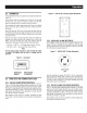

1.1 UNPACKING
• Removeall packagingmaterial.
• Removeseparateaccessorybox.
• Removethe generatorfrom carton.
1.1.1 ACCESSORYBOX
• 1-Owner's manual
• 1-Bottle of OilSAE30
• 3-Product RegistrationCards (English,Spanish,French)
• 1-BatteryCharger(electricstart only)
• 1-HandleAssembly
• 1-FrameFoot(E)
• 2-Never-FlatWheels(H)
• 1-Hardwarebag (containingthe following):
- 2-LongCurvedHeadBolts(A)
- 2-AcornNuts(B)
- 4-Flangednuts(C)
- 2-RubberFeet(D)
- 2-ShortBolts(F)
- 2-AxlePins(G)
- 2-Washers(1)
- 2-CotterPins(J)
- 2-FlangeNuts(electricstartonly)
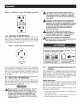
1.2 ASSEMBLY
The generator requires some assembly prior to using it. If
problems arise when assembling the generator,please call the
GeneratorHetplineat 1-888-436-3722.
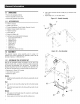
1.2.1 ASSEMBLINGTHEACCESSORYKIT
Refer to the instructions below and Figures 1A, 1B, and 1C to
installthe handle,feet, and wheels. Note: the handlecomponents
are already pre-assembled from the factory. The wheels are
designedto greatly improve the portability of the generator.You
will needthe following tools to properly installthe accessory kit:
• Ratchetand a 13mm [1/2"] socket
• 13mm [1/2"] boxwrench
• Needlenosepliers
Handle
1. Installthe handleassemblyto the frameby usingbolts (A) and
nuts (B).
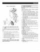
Feet
2. Use nuts (C) to mount the rubberfeet (D) to the foot bracket
(E).
3. Mountthe foot bracket (E)to the framewith two bolts (F) and
nuts (C).
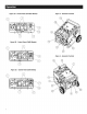
Wheels
4. Slideaxle pin (G)through wheel (H), washer (I), andthrough
the bracket on the frame.
5. Secureaxle pin (G)to the frame with the cotter pin (J).
6. Usea pliers andbendonetab of cotter pin (J) outwardto lock
into place.
7. Repeatsteps 5, 6, & 7 for other wheel.
Figure 1A - Handle Assembly
Figure 1B - Foot Assembly
I