
Manual
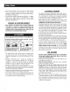
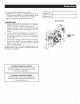
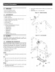
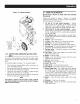
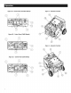
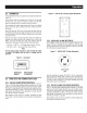
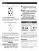

Figure lC - Wheel Assembly
BEND ONETAB
AFTERAXLE
PIN(G)IS
INSERTED _
THROUGH
THEFRAME
1.2.2 BATTERYCABLECONNECTION(ELECTRICSTART
ONLY)
The unit has been deliberately shipped with the battery cables
disconnected.Youwill needa lOmm wrenchto securethe battery
cables.
Toconnect the battery (see Figure17 for connectiondetails):
1. Cut off cable ties securing battery cables and remove red
covers from batteryterminals.
2. First,connectthe redcableto the positive (+) batteryterminal
with the bolt, lock washer andnut supplied.
3. Connect the black cable to the negative(-) battery terminal
with the bolt, lock washer andnut supplied.
4. Make sure all connectionsare secure. Slidethe rubber boots
over the terminals and connectionhardware.
NOTE:
if the battery is unable to start the engine, charge it with the
12V chargerincludedinthe accessory box (see the "Charginga
Battery"section for details).
2.1 KNOWTHEGENERATOR
Read the Owner'sManual and Safety Rules before operating
this generator.
Compare the generator to Figures 2 through 4 to become
familiarizedwith the locations of variouscontrols andadjustments.
Savethis manualfor future reference.
1. 120 Volt AC, 20 Amp, Duplex Receptacle - Supplies
electrical power for the operationof 120 Volt AC, 20 Amp,
single-phase, 60 Hz electrical lighting, appliance, tool and
motor loads. CARBmodels areequippedwith GFCIoutlets.
2. 120/240 Volt AC, 30 Amp LockingReceptacle - Supplies
electrical power for the operation of 120 and/or 240 Volt AC,
30 Amp, single-phase, 60 Hz, electrical lighting, appliance,
tool andmotor loads.
3. Circuit Breakers(AC) - Each receptacle is provided with a
push-to-reset circuit breakerto protect the generatoragainst
electrical overload.
4. Oil Drain- Useto drainengineoil.
5. Air Filter- Filtersintakeair as it is drawn into the engine.
6. ChokeKnob- Usedwhen startinga cold engine.
7. FuelTank- SeegeneratorSpecificationsfor tank capacity.
8. GroundingLug - Groundthe generatorto an approvedearth
groundhere. See"Groundingthe Generator"for details.
g. Run/Stop Switch - Controls the operationof the generator
(pullstart models).
gA. Start Switch - Used to start engine from the starter motor
(electricstart modelsonly).
10. Muffler - Quietsthe engine.
11. Handle - Pivot and retract for storage. Press the spring-
loadedbuttonto move handles.
12. Gas Cap- Fuelfill location.
13. FuelGauge- Showsfuel levelin tank.
14. Oil Fill- Add oil here.
15. Recoil Starter - Useto start enginemanually.
15. Fuel Shut Off - Valve betweenfuel tank and carburetor.
17. BatteryCharger Input -This receptacleallowsthe capability
to recharge the 12 volt DO storage battery provided with
the 12 Volt Adaptor Plug Charger which is included in the
Accessory Box. Located behindthe battery charger input is
a 1.50 Amp in-line fuse which is inside the control panelto
protect the battery (electric start models only).
18. Battery - Powersthe electric starter (electric start models
only).
lg. Hourmeter - Trackshours of operation.
28. Spark Arrestor - Reducesfire hazardsby containing sparks
(CARBmodels only).