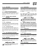
Owner’s Manual and Installation Instructions Air-cooled Recreational Vehicle Generator • Model No: 00941-3 IMPACT-36 plus II with Inverter This manual should remain with the unit.
INTRODUCTION Thank you for purchasing this generator by Generac Power Systems, Inc. This model is designed and manufactured to supply electrical power for recreational vehicles. ◆ READ THIS MANUAL THOROUGHLY If any portion of this manualis not understood, contact the nearest Generac Authorized Service Dealer for starting, operating, and servicing procedures.
Table of Contents IMPACT-36 plus II Recreational Vehicle Generator Part I – Owner’s Manual Part II – Installation Instructions Introduction ....................................................Inside Front Cover Safety Rules..................................................................................16 Read This Manual Thoroughly ............................................IFC Contents ..............................................................................IFC Operation and Maintenance ......
Safety Rules IMPACT-36 plus II Recreational Vehicle Generator SAVE THESE INSTRUCTIONS – The manufacturer suggests that these rules for safe operation be copied and posted in potential hazard areas of the recreational vehicle. Safety should be stressed to all operators and potential operators of this equipment. ! ! ! WARNING: The engine exhaust from this product contains chemicals known to the state of California to cause cancer, birth defects, or other reproductive harm.
Safety Rules IMPACT-36 plus II Recreational Vehicle Generator • When working on this equipment, remain alert at all times. Never work on the equipment when physically or mentally fatigued. • Inspect the generator regularly, and contact the nearest Generac Authorized Service Dealer immediately for parts needing repair or replacement. • Before performing any maintenance on the generator, disconnect its battery cables to prevent accidental startup.
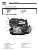
IMPACT 36 plus II Recreational Vehicle Generator Section 1 – General Information IMPACT-36 plus II Recreational Vehicle Generator 1.1 GENERATOR IDENTIFICATION Please record the following information from the generator DATA DECAL or information decal, located below the user control panel. 1. Model Number ____________________ 2. Serial Number __________________ 3. kW Rating__________________________ 4. Rated Voltage __________________ 5. Phase ______________________________ 6.
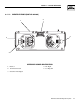
Section 1 – General Information IMPACT-36 plus II Recreational Vehicle Generator ◆ 1.1.2 INVERTER FEATURES (PART NO. 0D4885) 1 2 3 5 4 REFERENCE NUMBER IDENTIFICATION 1. Inverter 4. DC Input 2. 12 Pin Connection 5. Cooling Fan 3. Customer AC Output Generac® Power Systems, Inc.
Section 1 – General Information IMPACT-36 plus II Recreational Vehicle Generator 1.2 GENERATOR APPLICABILITY These generators have been designed and manufactured for supplying electrical power for recreational vehicles. Do not modify the generator or use it for any application other than for what it was designed. If there are questions pertaining to its application, write or call the factory. Do not use the unit until advised by a competent authority.
Section 2 – Operation IMPACT-36 plus II Recreational Vehicle Generator ◆ 1.4.5 HOUR METER ◆ 1.5.4 LOW VOLTAGE Indicates the time the engine-generator has operated, in hours and tenths of hours. Use the hourmeter along with the periodic maintenance schedule for the generator set. The computer monitors the voltage output of the generator. If voltage sensors indicate that voltage has dropped below a preset level, the engine will automatically shut down.
Section 2 – Operation IMPACT-36 plus II Recreational Vehicle Generator ◆ 2.1.4 COOLING AND VENTILATING AIR Air inlet and outlet openings in the generator compartment must be open and unobstructed for continued proper operation. Without sufficient cooling and ventilating air flow, the engine-generator quickly overheats, which causes it to automatically shutdown. Overheating could also damage the unit or the vehicle. ◆ 2.1.
Section 2 – Operation IMPACT-36 plus II Recreational Vehicle Generator 2.4 APPLYING LOADS TO GENERATOR When applying electrical loads to the generator, observe these guidelines: • Before applying electrical loads, let the generator stabilize and warm up for a minute or two. • DO NOT overload the generator. ◆ 2.4.1 LETTING ENGINE STABILIZE The generator supplies correctly rated frequency and voltage only at the proper governed speed.
Section 3 – Maintenance IMPACT-36 plus II Recreational Vehicle Generator 3.1 MAINTENANCE This section includes information about simple maintenance which includes the following tasks: • • • • • Checking engine oil level. Changing engine oil. Changing oil filter. Air cleaner maintenance. Cleaning the air intake screen. Cleaning spark arrestor. • Cleaning spark plug. Replacing fuel filter. Servicing inverter. 3.
Section 3 – Maintenance IMPACT-36 plus II Recreational Vehicle Generator 3.5 ENGINE AIR CLEANER Paper Filter: Once every 25 operating hours or once each year (whichever comes first), clean or replace the paper filter (Figure 3.3). Follow the steps on page 12. 3.7 ENGINE SPARK PLUG Clean engine spark plug and set gap to 0.030 inch (0.76mm) every 100 hours of operation (Figure 3.5). Clean by scraping or wire brushing and washing with commercial solvent. DO NOT BLAST CLEAN SPARK PLUG. Figure 3.
Section 3 – Maintenance IMPACT-36 plus II Recreational Vehicle Generator 3.11 SERVICE AND ADJUSTMENTS ! Do NOT use a forceful spray of water to clean the generator. Water will enter the generator interior and cause problems, and may also contaminate the generator fuel system. 3.10 BATTERY All lead-acid storage batteries will discharge when not in use. Inspect the generator battery as follows: ◆ 3.10.1 ONCE WEEKLY Inspect battery posts and cables for tightness, corrosion.
Section 3 – Maintenance IMPACT-36 plus II Recreational Vehicle Generator 2. When valve clearance is correct, hold the pivot ball stud with the allen wrench and tighten the rocker arm jam nut with a crows foot. Tighten the jam nut to 65-85 inch-pounds torque. After tightening the jam nut, recheck valve clearance to make sure it did not change (Figure 3.9). Figure 3.9 — Tightening Jam Nut 3.
Section 4 – Notes IMPACT-36 plus II Recreational Vehicle Generator 14 Generac® Power Systems, Inc.
PART II – INSTALLATION INSTRUCTIONS DANGER ONLY QUALIFIED ELECTRICIANS OR CONTRACTORS SHOULD ATTEMPT INSTALLATION!!
Safety Rules IMPACT-36 plus II Recreational Vehicle Generator ! DANGER: For fire safety, installation of a generator into a recreational vehicle must comply strictly with NFPA 70 (latest edition), “National Electrical Code”, Article 551, and NFPA 1192 (latest edition), “Standard for Recreational Vehicles”. In addition, installation must comply with the manufacturer’s instructions and recommendations.
Safety Rules IMPACT-36 plus II Recreational Vehicle Generator ELECTRICAL HAZARDS FIRE HAZARDS • The generator covered by this manual produces dangerous electrical voltages that can cause fatal electrical shock. Avoid contact with bare wires, terminals, connections, etc., while the unit is running. Ensure all appropriate covers, guards, and barriers are in place before operating the generator. If work must be done around an operating unit, stand on an insulated, dry surface to reduce shock hazard.
Section 1 – General Information IMPACT-36 plus II Recreational Vehicle Generator 1.1 PURPOSE AND SCOPE OF THE MANUAL These Installation Instructions have been prepared especially for the purpose of familiarizing installers and owners of the applicable equipment with the product's installation requirements. Give serious consideration to all information and instructions in the manual, both for safety and for continued reliable operation of the equipment.
Section 2 – Installation IMPACT-36 plus II Recreational Vehicle Generator 2.1 LOCATION AND SUPPORT ◆ 2.1.1 GENERATOR LOCATION The most desirable location for the generator set is between the vehicle's main frame members However, this is seldom possible. Most units must be installed on the side of the vehicle and are difficult to reinforce.
Section 2 – Installation IMPACT-36 plus II Recreational Vehicle Generator ◆ 2.1.4 GENERATOR RESTRAINT Use four 5/16"-18 hardened steel bolts (Grade 5) to fasten the generator to the supporting frame or the support tubing. These bolts must pass through (a) the generator mounting base, (b) the compartment floor, if a compartment is used, and (c) the supporting framework (Figure 2.3). All bolts must be long enough so that when tight, at least 3 threads are visible past the retaining lock nuts.
Section 2 – Installation IMPACT-36 plus II Recreational Vehicle Generator ◆ 2.2.1 COMPARTMENT SIZE Plan the compartment size carefully. Provide a minimum of at least 1 inch (2” recommended) of clearance between the generator and compartment walls and 1 inch (2” recommended) of clearance between the generator and the ceiling AFTER the compartment has been lined with metal, and AFTER sound insulation has been installed (Figure 2.5).
Section 2 – Installation IMPACT-36 plus II Recreational Vehicle Generator ◆ 2.2.3 SOUND INSULATING MATERIALS ◆ 2.2.4 COMPARTMENT FLOOR CUTOUTS Once installers have determined that compartments are properly constructed and metal lined, they can add acoustical material. This may include additional sealant or insulating material, to reflect noise away from the vehicle interior. Provide openings in the generator compartment for the following items (Figure 2.
Section 2 – Installation IMPACT-36 plus II Recreational Vehicle Generator ◆ 2.2.5 ACOUSTICS If excessive noise levels should become a problem, the installer may wish to consider the following: • Using special sound insulating materials. • Construction of a special noise abatement compartment. IMPORTANT: ANY METHOD USED TO REDUCE NOISE MUST NOT ADVERSELY AFFECT THE FLOW OF COOLING AND VENTILATING AIR INTO OR OUT OF THE COMPARTMENT.
Section 2 – Installation IMPACT-36 plus II Recreational Vehicle Generator ◆ 2.3.2 COOLING AIR INLET OPENINGS Figure 2.11 — Suspended Mount Inlet Door Provide three air inlet openings, whether the generator is housed in a conventional compartment or not. Two of the openings should be 10 square inches and located as shown in Figure 2.10. The third opening should provide for a minimum of 40 square inches unrestricted and be located lower on the compartment door.
Section 2 – Installation IMPACT-36 plus II Recreational Vehicle Generator ◆ 2.3.3 COMPENSATING FOR RESTRICTIONS 2.4 Such materials as screening, louvers, or expanded metal can restrict the free flow of air. Compensate for this restriction by making the actual air opening proportionately larger. ◆ 2.4.1 PARTS NOT INCLUDED IN FUEL SYSTEM Some materials may offer only a 60 percent “free air inlet area.” Other more efficient materials may provide up to a 90 percent free air inlet area.
Section 2 – Installation IMPACT-36 plus II Recreational Vehicle Generator ◆ 2.4.2 SOME IMPORTANT CONSIDERATIONS When installing an LP gas system, consider seriously the following items: • All fittings, lines, hoses and clamps must be tight and free of leaks. Apply a pipe sealant to threads when assembling threaded connections. This reduces the possibility of leakage. Test the entire fuel system for leaks, using approved test methods.
Section 2 – Installation IMPACT-36 plus II Recreational Vehicle Generator • The regulator must be sensitive to venturi throat pressure changes throughout the operating range. • The regulator must be properly adjusted so it will stop the flow of gas when the engine is not running (no air flow through the carburetor). • The slightest air flow (and vacuum) in the venturi throat should move the regulator valve off its seat and permit gas to flow.
Section 2 – Installation IMPACT-36 plus II Recreational Vehicle Generator Failure to provide and maintain a spark arrestor may be in violation of the law. If this generator is used on any forest covered, brush covered, or grass covered unimproved land, provide a spark arrestor. The vehicle owner or operator must maintain this device in good condition. In the State of California, the preceding is required by law (Section 4442 of the California Public Resources Code). Other states may have similar laws.
Section 2 – Installation IMPACT-36 plus II Recreational Vehicle Generator • Wiring must be of adequate size, with approved insulative qualities, and properly supported. • Conduit and wire openings into generator compartment (if used) must be vapor-sealed, to prevent entry of flammable, explosive or poisonous gases into the vehicle. Figure 2.19 — Inverter J Box for AC Output ◆ 2.6.1 WIRING • Wiring should be of stranded copper to reduce chance that vibration may cause breakage.
Section 2 – Installation IMPACT-36 plus II Recreational Vehicle Generator Figure 2.20 — Transfer Switch Isolation Method INVERTER POWER SUPPLY CORD POWER CORD FOR DOCKSIDE POWER Figure 2.21 — Installation with Isolation Receptacle INVERTER 30 Generac® Power Systems, Inc.
Section 2 – Installation IMPACT-36 plus II Recreational Vehicle Generator ◆ 2.6.6 SENSING HARNESS A sensing harness has been provided with the generator to connect to the inverter (Figure 2.22). It is 12 feet long, however, it is also available in a 24 foot length: Model # 04612-0. The four (4) DC power wires (Red, Blue Black, and Green) may be cut to the desired length to meet the installation (see Figure 2.22). ! 2.7 DO NOT in any way cut or shorten the sensing harness.
Section 2 – Installation IMPACT-36 plus II Recreational Vehicle Generator CABLE LENGTH in Feet (Meters) CABLE SIZE 0 to 10 (0 to 3) 11 to 15 (3.4 to 4.5) 16 to 20 (4.9 to 6) 2* 0 000 * For warm weather, use No. 2 cable up to 20 feet. ◆ 2.7.3 BATTERY CABLE CONNECTIONS 1. Connect the battery cable from the battery post or terminal indicated by a POSITIVE, POS or (+) to the large lug on the starter contactor as indicated in Figure 2.23. 2.
Section 3 – Post-installation Start-up Checks IMPACT-36 plus II Recreational Vehicle Generator CHECKS 3.1 POST INSTALLATION TESTS The air cooled Impact-36 plus II generator set was factory tested and adjusted using gasoline as fuel.The air cooled Impact-34 plus II generator set was factory tested and adjusted using LP gas as fuel. It is not required to adjust the unit any further except under special circumstances. ! 3.2 Do not make any unnecessary adjustments.
Section 3 – Post-installation Start-up Checks IMPACT-36 plus II Recreational Vehicle Generator 3.5 INSTALLATION CHECKLIST ◆ LOCATION AND SUPPORT ❑ Generator is properly located. ❑ Generator is properly supported. ❑ Generator is properly restrained. ◆ GENERATOR COMPARTMENT ◆ EXHAUST SYSTEM ❑ Exhaust system complies with all applicable codes. ❑ Exhaust system is properly and safely installed. ◆ ELECTRICAL CONNECTIONS ❑ Connections comply with local code requirements and all National Electrical Codes.
Section 4 – Troubleshooting IMPACT-36 plus II Recreational Vehicle Generator 4.1 TROUBLESHOOTING GUIDE PROBLEM CAUSE CORRECTION 1. 2. Fuse is blown. Loose corroded or defective battery cables. Defective engine Start/Stop switch. Defective starter contactor. Defective starter motor. Low or defective Battery 1. 2. 1. 2. 3. 4. 5. 6. Out of fuel. Fuel pump is defective (Gasoline), OR, fuel solenoid is defective (LP). Open Wire #14 from Eng. Control Bd. Engine is flooded. Spark plug defective.
Section 5 – Notes IMPACT-36 plus II Recreational Vehicle Generator 36 Generac® Power Systems, Inc.
Section 6 — Electrical Data IMPACT-36 plus II Recreational Vehicle Generator Major Features and Dimensions – Drawing No. 0E7561 Generac® Power Systems, Inc.
Section 6 — Electrical Data IMPACT-36 plus II Recreational Vehicle Generator Wiring Diagram and Schematic – Drawing No. 0D4947-B 38 Generac® Power Systems, Inc.
Section 6 — Electrical Data IMPACT-36 plus II Recreational Vehicle Generator Wiring Diagram and Schematic – Drawing No. 0D4947-B Generac® Power Systems, Inc.
Section 7 — Exploded Views and Parts Lists 48 17 16 26 6 3 10 4 27 40 Generac® Power Systems, Inc. 36 1 44 47 8 35 22 2 28 49 9 13 2 21 11 9 40 5 41 8 14 15 9 41 9 31 19 26 19 46 43 31 27 25 12 14 22 42 7 23 38 30 37 20 22 10 33 24 45 34 51 50 IMPACT-36 plus II Recreational Vehicle Generator Control Panel – Drawing No.
Section 7 — Exploded Views and Parts Lists IMPACT-36 plus II Recreational Vehicle Generator Control Panel – Drawing No. 0E7560 ITEM PART NO. QTY.
Section 7 — Exploded Views and Parts Lists IMPACT-36 plus II Recreational Vehicle Generator Impact-34 plus II Sheet Metal – Drawing No. 0A9193-K 1 75 30 44 22 4 3 38 3 11 2 4 3 11 5 20 21 24 43 22 2 25 39 3 3 34 44 65 37 33 30 53 29 27 2 47 30 59 67 36 68 81 51 35 49 57 7 6 8 23 43 5 50 60 61 55 51 78 32 63 40 41 64 19 42 5 12 71 26 2 18 5 31 66 77 78 80 5 17 73 54 74 70 76 42 Generac® Power Systems, Inc.
Section 7 — Exploded Views and Parts Lists IMPACT-36 plus II Recreational Vehicle Generator Impact-34 plus II Sheet Metal – Drawing No. 0A9193-K ITEM 1 2 3 4 5 6 7 8 9 11 12 17 18 19 20 21 22 23 24 25 26 27 29 30 31 32 33 34 35 36 37 38 39 40 41 42 PART NO. QTY.
Section 7 — Exploded Views and Parts Lists 48 42 38 32 51 52 49 3 14 10 6 7 2 1 7 5 50 8 1 19 34 17 18 59 13 13 33 22 25 23 24 11 28 4 17 36 37 58 40 39 21 54 53 31 30 26 43 44 45 47 46 IMPACT-36 plus II Recreational Vehicle Generator GN 220 RV Long Block – Drawing No. 0A6202-G 44 Generac® Power Systems, Inc.
Section 7 — Exploded Views and Parts Lists IMPACT-36 plus II Recreational Vehicle Generator GN 220 RV Long Block – Drawing No. 0A6202-G ITEM 1 2 3 4 5 6 7 8 10 11 13 14 17 18 19 21 22 23 24 25 26 28 30 31 32 33 34 36 37 38 39 40 42 43 44 45 46 47 48 49 50 51 52 53 54 58 59 PART NO.
Section 7 — Exploded Views and Parts Lists IMPACT-36 plus II Recreational Vehicle Generator Generator – Drawing No. 0D4945-A 46 Generac® Power Systems, Inc.
Section 7 — Exploded Views and Parts Lists IMPACT-36 plus II Recreational Vehicle Generator Generator – Drawing No. 0D4945-A ITEM 1 2 3 4 5 6 7 8 9 10 11 12 13 14 15 16 17 18 19 20 21 22 23 24 25 26 27 28 29 30 31 32 33 34 35 36 37 38 39 40 41 42 43 44 45 46 47 48 49 50 51 52 53 PART NO. QTY.
Section 8 – Warranty IMPACT-36 plus II Recreational Vehicle Generator CALIFORNIA AND FEDERAL EMISSION CONTROL WARRANTY STATEMENT YOUR WARRANTY RIGHTS AND OBLIGATIONS The California Air Resources Board (CARB) and the United States Environmental Protection Agency (EPA), together with Generac Power Systems, Inc. (Generac), are pleased to explain the Emission Control System Warranty on your new engine.
Section 8 – Warranty IMPACT-36 plus II Recreational Vehicle Generator EMISSION CONTROL SYSTEM WARRANTY Emission Control System Warranty (ECS Warranty) for 1997 and later model year engines: (a) Applicability: This warranty shall apply to 1997 and later model year engines. The ECS Warranty Period shall begin on the date the new engine or equipment is purchased by/delivered to its original, end-use purchaser/owner and shall continue for 24 consecutive months thereafter.
Section 8 – Warranty IMPACT-36 plus II Recreational Vehicle Generator GENERAC POWER SYSTEMS’ THREE-YEAR LIMITED WARRANTY FOR GUARDIAN RECREATIONAL VEHICLE GENERATORS NOTE: ALL UNITS MUST BE INSTALLED BY GENERAC POWER SYSTEMS AUTHORIZED SERVICE FACILITIES. For a period of 3 (three) years of operation from the date of original sale, Generac Power Systems, Inc.