MODEL: 005802-2 Owner's Manual XG Professional Series Portable Generator DEADLY EXHAUST FUMES! ONLY use OUTSIDE far away from windows, doors and vents! INTENDED FOR USE IN CRITICAL LIFE NOT SUPPORT APPLICATIONS. SAVE this Manual. Provide this manual to any operator of the generator. www.generac.
Table of Contents Introduction............................................................. 1 Maintenance ......................................................... 11 Read this Manual Thoroughly ................................. 1 3.1 3.2 3.3 Safety Rules ........................................................... 1 Standards Index .............................................................3 General Information ................................................ 4 1.1 1.2 Unpacking ....................
Safety Rules INTRODUCTION Thank you for purchasing this model by Generac Power Systems, Inc. This model is a compact, high performance, air-cooled, engine driven generator designed to supply electrical power to operate electrical loads where no utility power is available or in place of utility due to a power outage. READ THIS MANUAL THOROUGHLY If any portion of this manual is not understood, contact the nearest Authorized Dealer for starting, operating and servicing procedures.
Safety Rules • Never use the generator or any of its parts as a step. Stepping on the unit can stress and break parts, and may result in dangerous operating conditions from leaking exhaust gases, fuel leakage, oil leakage, etc. • On electric start models, disconnect the POSITIVE (+) battery cable from the engine starter OR the NEGATIVE (-) battery cable from the battery terminal, whichever is easier, before transporting the generator.
Safety Rules • Do not insert objects through unit’s cooling slots. • Do not operate the generator if connected electrical devices overheat, if electrical output is lost, if engine or generator sparks or if flames or smoke are observed while unit is running. • Keep a fire extinguisher near the generator at all times.
General Information 1.1 UNPACKING 1.2.1 ASSEMBLING THE WHEEL KIT AND FRAME FOOT • Remove all packaging material. • Remove separate accessory box. • Remove carton off the generator. The wheel kit is designed to greatly improve the portability of the generator. You will need the following tools to install the wheel kit: 1/2" (13mm) wrench and a socket wrench with a 1/2" (13mm) socket. NOTE: 1.1.1 ACCESSORY BOX Check all contents (Figure 1).
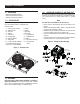
Operation 2.1 KNOW THE GENERATOR Read the entire Owner’s Manual and Safety Rules before operating this generator. Compare the generator to Figures 3 through 6 to become familiarized with the locations of various controls and adjustments. Save this manual for future reference. 24. Roll Over Valve - Passes fuel vapors to the engine. 25. Evap Hose - Installed between the roll over valve and the engine. Figure 3 – Generator & Engine Locations 1. Choke Knob – Used when starting a cold engine (Pull/Push). 2.
Operation 2.1.1 BATTERY CONNECTION NOTE: The battery shipped with the generator has been fully charged. A battery may lose some of its charge when not in use for prolonged periods of time. If the battery is unable to crank the engine, plug in the 12V charger included in the accessory box (see the Charging the Battery section). RUNNING THE GENERATOR WILL CHARGE THE BATTERY. The positive battery wire was deliberately left detached for shipping.
Operation 2.3.4 120/240 VAC, 50 AMP RECEPTACLE Use a NEMA 14-50 plug with this receptacle. Connect a 4-wire cord set rated for 250 Volts AC at 50 Amps to the plug (Figure 6). Use this receptacle to operate 120/240 Volt AC, 60 Hz electrical loads requiring up to 10,000 watts (10.0 kW) of power at 41.6 Amps for 240 volts or two independent 120 Volt loads. This receptacle is protected by a 42 Amp 2-pole circuit breaker. exhaust system must be properly maintained.
Operation NOTE: Because the generator equipment ground is bonded to the AC neutral wires in the generator (see Figure 8), either a 3-pole transfer switch or a 2 pole transfer switch with a switching neutral kit is required to connect this generator to a building load. In this application the generator becomes a separately derived system (see NEC 250.20 (D)), and must be grounded in accordance with the national or local electrical code requirements.
Operation Disc Sander (9") . . . . . . . . . . . . . . . . . . . . . . . . . . . . . . . . . . . . 1200 Edge Trimmer . . . . . . . . . . . . . . . . . . . . . . . . . . . . . . . . . . . . . . . 500 Electric Blanket . . . . . . . . . . . . . . . . . . . . . . . . . . . . . . . . . . . . . . 400 Electric Nail Gun . . . . . . . . . . . . . . . . . . . . . . . . . . . . . . . . . . . . 1200 Electric Range (per element) . . . . . . . . . . . . . . . . . . . . . . . . . . . 1500 Electric Skillet . . . . . . . .
Operation Figure 8 – Fuel Fill Level Figure 10 – Fuel Shut-off Valve DO NOT FILL ABOVE LIP! 2.8 COLD WEATHER OPERATION/DE-ICER Figure 11 – Choke Operation Under certain weather conditions (temperatures below 40° F (4° C) and a high dew point), the engine may experience icing of the carburetor and/or the crankcase breather system. To eliminate this problem, this generator engine is fitted with a winter/summer valve. This directs hot air into the carburetor during cold weather operation.
Maintenance • Press and hold the Start/Run/Stop switch in the “Start” position. The engine will crank and attempt to start. When the engine starts, release the switch to the run position. • When the engine starts, push choke knob to “1/2 Choke” position until the engine runs smoothly and then fully in to the “Run” position. If engine falters, pull choke knob back out to “1/2 Choke” position until the engine runs smoothly and then to “Run” position.
Maintenance 3.3.2 ENGINE SPECIFICATIONS Rated Horsepower @ 3600 RPM ................................................. 18 Hp Displacement ............................................................................... 530cc Spark Plug Type ........................................... NGK BPR6HS or Equivalent Spark Plug Gap ............................................... 0.030 inch or (0.76 mm) Gasoline Capacity .......................................................... 10 U.S. gallons Oil Type................
Maintenance • Coat gasket of new filter with clean engine oil. Turn filter clockwise until gasket contacts lightly with filter adapter. Then tighten an additional 3/4 turn. • Fill engine with recommended oil and replace the dipstick. (See “Before Starting the Generator” for oil recommendations). • Wipe up any spilled oil. • Dispose of used oil at a proper collection center. Figure 13 – Air Filter 3.4.6 REPLACING THE SPARK PLUG(S) Use NGK BPR6HS spark plugs or equivalent. Replace the plugs once each year.
Battery Service Figure 14 – Spark Arrestor Screen • Remove spark plugs and pour about 1/2 ounce (15 ml) of engine oil into each cylinder. • Install and tighten spark plugs. Do not connect the spark plug wires • Clean the generator outer surfaces. Check that cooling air slots and openings on generator are open and unobstructed. • Store the unit in a clean, dry place. 3.9 OTHER STORAGE TIPS 3.7 GENERAL The generator should be started at least once every seven days and be allowed to run at least 30 minutes.
Troubleshooting 5.1 TROUBLESHOOTING GUIDE PROBLEM CAUSE CORRECTION Engine is running, but no AC output is available. 1. 2. 3. 4. 5. Circuit breaker is open. Poor connection or defective cord set. Connected device is bad. Fault in generator. GFCI trips the 20 Amp outlet. 1. 2. 3. 4. 5. Reset circuit breaker. Check and repair. Connect another device that is in good condition. Contact Authorized Service Facility. Repair the "short" and reset the GFCI.
Warranty U.S. EPA EMISSION CONTROL WARRANTY STATEMENT YOUR WARRANTY RIGHTS AND OBLIGATIONS The United States Environmental Protection Agency (EPA) and Generac Power Systems, Inc. (Generac) are pleased to explain the Emission Control System Warranty (ECS Warranty) on your new 2011 and later equipment. New equipment that use small spark-ignited engines must be designed, built, and equipped to meet stringent anti-smog standards for the federal government.
Warranty EMISSION CONTROL SYSTEM WARRANTY Emission Control System Warranty (ECS Warranty) for equipment using small spark-ignited engines: (a) Applicability: This warranty shall apply to equipment that uses small off-road engines.
Warranty GENERAC POWER SYSTEMS “TWO YEAR” LIMITED WARRANTY FOR XG SERIES PORTABLE GENERATORS For a period of two (2) years from the date of original sale, Generac Power Systems, Inc. (Generac) warrants its XG Series generators will be free from defects in materials and workmanship for the items and period set forth below.
Garantía GARANTÍA LIMITADA DE “DOS AÑOS” DE SISTEMAS DE POTENCIA GENERAC PARA GENERADORES PORTÁTILES SERIE XG Por un periodo de dos años (2) desde la fecha de la venta original, Generac Power Systems, Inc. (Generac) garantiza sus generadores serie XG como libres de defectos en materiales y mano de obra por los ítems y periodos indicados abajo.
Garantía GARANTÍA DEL SISTEMA DE CONTROL DE EMISIONES Garantía del Sistema de Control de Emisiones [ECS, por sus siglas en inglés] (garantía del ECS) para equipos que usan pequeños motores encendidos con chispa: (a) Aplicación: Esta garantía se aplicará a los equipos que utilizan pequeños motores no para vehículos.
Garantía DECLARACIÓN DE GARANTÍA DE CONTROL DE EMISIONES DE LA EPA EE.UU. SUS DERECHOS DE GARANTÍA Y OBLIGACIONES La Agencia de Protección Ambiental (EPA) de los EE.UU. y Generac Power Systems, Inc. (Generac) se complacen en explicar la garantía del Sistema de Control de Emisiones en su nuevo equipo de 2011 y posteriores.
Localización y corrección de fallas 5.1 GUÍA DE LOCALIZACIÓN Y CORECCIÓN DE FALLAS 1. La válvula de corte de combustible está en OFF. El motor no arranca, o arranca y funciona mal. 1. Recargue o reemplace la batería (consulte "No salida DC del cargador de la batería" en el fondo de la guía.). 1. la batería está muerta o desconectada. El motor no enciende. 1. 2. 3. 4. Cortocircuito en una carga conectada. El generador está sobrecargado. La velocidad del motor es muy baja.
Servicio de la batería Figura 14 — Filtro del supresor de chispas TORNILLO AUTORROSCANTE • Quite las bujías y vierta cerca de 1/2 onza (15 ml) de aceite de motor en cada cilindro. • Instale y apriete las bujías. No conecte los cables de la bujía. • Limpie las superficies externas del generador. Compruebe que las ranuras y aberturas del aire de enfriamiento en el generador estén abiertas y sin obstáculos. • Almacene la unidad en un lugar limpio y seco. 3.
• Recubra la junta del nuevo filtro con aceite de motor limpio. Gire el filtro a la izquierda hasta que la junta haga contacto ligeramente con el adaptador del filtro. Luego apriete 3/4 de vuelta adicional. • Llene el motor con el aceite recomendado y reemplace la varilla de aceite. (Consulte la sección "Antes de arrancar el generador" para conocer las recomendaciones acerca del aceite). • Limpie el aceite derramado. • Disponga del aceite usado en un centro de recolección apropiado. 3.4.
Mantenimiento 3.3.2 ESPECIFICACIONES DEL MOTOR Caballos de fuerza nominales a 3600 RPM .................................. 18 Hp Desplazamiento............................................................................ 530cc Tipo de bujía ................................................NGK BPR6HS o equivalente Espaciamiento de la bujía.......................... 0.030 pulgadas o (0.76 mm) Capacidad de combustible ................................. 10 galones americanos Tipo de aceite .......................
• Presione y mantenga apretado el interruptor Arranque/Marcha/Parada en la posición "Arranque". El motor intentará arrancar. Cuando lo haga, ponga el interruptor en la posición Marcha y suéltelo. • Durante el arranque, mueva la palanca del estrangulador a la posición “1/2 Choke” ("1/2 estrangulación") hasta que el motor arranque suavemente y luego por completo a la posición "Run" ("Arranque").
Operación Figure 8 – Nivel de llenado del combustible Figura 10 - Válvula de corte de combustible ¡NO LLENAR POR ENCIMA DEL BORDE! 2.8 OPERACIÓN EN CLIMA FRÍO/DESCONGELADOR Figura 11 – Operación del estrangulador Bajo ciertas condiciones de clima (temperaturas abajo de 40° F (4° C) y un alto punto de rocío), el motor puede experimentar congelamiento del carburador y/o el sistema respirador del cárter. Para eliminar este problema, este generador está equipado con una válvula de invierno/ verano.
*Freezer . . . . . . . . . . . . . . . . . . . . . . . . . . . . . . . . . . . . . . . . . . . 700 *Ventilador de horno (3/5 HP) . . . . . . . . . . . . . . . . . . . . . . . . . . 875 *Dispositivo de apertura de puerta de garaje . . . . . . . . . . 500 a 750 Secadora para cabello . . . . . . . . . . . . . . . . . . . . . . . . . . . . . . . 1200 Taladro de mano . . . . . . . . . . . . . . . . . . . . . . . . . . . . . . . 250 a 1100 Cortadora de setos . . . . . . . . . . . . . . . . . . . . . . . . . . . .
Operación Cómo poner a tierra el generador en una aplicación de respaldo de edificio ADVERTENCIA El Código Eléctrico Nacional exige que el marco y las partes conductoras eléctricas externas de este generador sean conectadas apropiadamente a una toma a tierra aprobada. Los códigos eléctricos locales pueden también requerir que la unidad se ponga a tierra adecuadamente (Figura 7). Para eso, la conexión de un cable de cobre trenzado No.
2.3.4 RECEPTÁCULO DE 120/240 VAC, 50 AMPERIOS Use un tomacorriente NEMA 14-50 con este receptáculo Conecte una cable de 4 hilos con capacidad de 250 voltios a 50 amperios al tomacorriente. (Figure 6). Use este receptáculo para operar cargas eléctricas de 120/240 voltios AC, monofásicas de 60 Hz, que requieran hasta 10000 vatios (10.0 kW) de potencia a 41.6 amperios para 240 voltios o dos cargas independientes de 120 voltios.
Operación 2.1.1 CONEXIÓN DE LA BATERÍA NOTA: La batería que se envía con el generador ha sido cargada completamente. Una batería puede perder parte de su carga cuando no está en uso por períodos prolongados. Si la batería es incapaz de arrancar el motor, conecte el cargador de 12 voltios que se incluye en la caja de accesorios (consulte la sección "Cómo cargar la batería"). PONER EN MARCHA EL GENERADOR CARGARÁ LA BATERÍA.
2.1 CONOZCA EL GENERADOR Lea el Manual del Propietario y las Reglas de Seguridad antes de poner el generador en funcionamiento. Compare el generador con las Figuras 3 a 6 para familiarizarse con las ubicaciones de los diferentes controles y ajustes Conserve este manual para futuras referencias. 1. 2. 3. 4. 5. 6. 7. 8. 9. 10. 11. 12. 13. 14. 15. 16. 17. 18. 19. 20. 21. 22. 23. Operación 24. Válvula de inversión - Pasa los vapores de combustible al motor. 25.
Información general El kit de rueda está diseñado para mejorar grandemente la portabilidad del generador. Usted necesitará las siguientes herramientas para instalar apropiadamente el kit de ruedas: Llave de 1/2" (13mm) y una llave de dado con un dado de 1/2" (13mm). • Retire todo el material de empaque. • Retire la caja de accesorios. • Retire la caja de cartón del generador. 1.2.1 1.1 DESEMPAQUE 1.1.
• Limpie los derrames de combustible o aceite inmediatamente. Asegúrese de que no se dejen materiales combustibles sobre o cerca del generador. Mantenga el área alrededor del generador limpia y libre de desechos y deje un espacio de cinco (5) pies a cada lado para permitir la adecuada ventilación del generador. • No inserte objetos a través de las ranuras de enfriamiento de la unidad.
Reglas de seguridad • Nunca utilice el generador o ninguna de sus piezas como escalón. Si se para sobre la unidad puede ejercer presión y romper piezas, y esto puede generar condiciones de funcionamiento peligrosas como fugas de gases de escape, fugas de combustible, fugas de aceite, etc. • En los modelos con arranque eléctrico, desconecte el cable POSITIVO (+) de la batería del motor de arranque O el cable NEGATIVO (-) del terminal de la batería, lo que sea más fácil, antes de transportar el generador.
INTRODUCCIÓN Gracias por comprar este generador portátil de Generac Power Systems, Inc. Este modelo es un generador compacto, de alto rendimiento, enfriado por aire y accionado por un motor que está diseñado para suministrar corriente eléctrica para impulsar cargas eléctricas donde no esté disponible el servicio público eléctrico o en lugar del servicio público eléctrico por un apagón.
Contenido 3.1 3.2 3.3 Lea este manual en su totalidad............................. 1 Mantenimiento ...................................................... 11 Introducción ............................................................ 1 Reglas de Seguridad .............................................. 1 Índice de normas ...........................................................3 Información general................................................ 4 1.1 1.2 Desempaque .....................................
MODELO: 005802-2 Manual del Usuario Generador portátil serie XG Profesional DOS AÑOS DE GARANTÍA LIMITADA PELIGRO ¡HUMOS DE ESCAPE MORTALES! ¡Utilícelo SOLAMENTE al AIRE LIBRE y lejos de ventanas, puertas y respiraderos! NO DISEÑADO PARA SER USADO EN APLICACIONES SOPORTE DE VIDA CRÍTICA. DE GUARDE este Manual. Proporcione este manual a cualquier operador del generador. www.generac.