
Install Drawing

BACK
E1
T1
N2
N1
23
15B
0
(194)
0
194
23
N1
N2
T1
INSTALLATION INSTRUCTIONS
ENGINE/BATTERY HEATER KIT FOR
CORE POWER
P/N: 0H5992 rev B
Figure 3
Figure 2
Figure 1
Connect
the two-pin
plug and route
through grommet
of connect box.
Apply these connections
to the Core Power
terminal blocks.
To install the battery/engine heater:
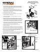
1. Verify a unit that has cooled completely. Turn the latches to lift and remove
the roof on the unit. Put the engine start switch in the “OFF” position and
remove the 7.5A main fuse from the fuse holder. Disconnect (by using the
transfer switch) any AC inputs to the unit.
2. Remove the side panel. Remove the NEGATIVE (-) battery cable first and
then the POSITIVE (+) battery cable from the battery. Remove the battery
from the unit (Figure 1). Using a clean towel, wipe the bottom of the battery
to remove any dirt, oil or contaminants.
3. Place the heater pad under the battery (Figure 2).
4. Place the battery in the unit. Connect the POSITIVE (+) battery cable first
and then the NEGATIVE (-) battery cable.
5. Connect the two-pin plug to one of the plug equipped leads on the kit’s
wiring harness. (Figure 2).
6. Remove the oil drain hose free from retaining clip. Remove the cap from
the hose and drain the oil into a suitable container. After the oil has drained,
replace the cap onto the end of the oil drain hose. Remove the existing oil filter
and replace using the oil filter provided in the kit. Retain the hose in the clip.
Locate and remove the socket plug using an 8 mm allen wrench (Figure 4).
7. Carefully thread and install the oil heater into the drain plug hole and tighten
with an 11/16” wrench. Refill the crankcase with the correct engine oil; refer
to the owner’s manual for the correct viscosity and amount.
8. Connect the two-pin plug to the other plug equipped lead on the kit’s
wiring harness. (Figure 4).
9. Route the wires along frame (Battery side), passing them over the intake boot
for the alternator. Pass the wires through the Customer Connect bushing with
yellow N1 and N2 wires and bring them to the 240 VAC terminal block (Figure 3).
10. Connect both the leads to the 240 VAC Input Sense terminal block (N1 and N2).
Press on top of spring loaded terminal block and insert harness leads.
HEATERS REQUIRE 240 VAC TO OPERATE!
11.
Replace the side panel removed in Step 2. Replace the 7.5A DC fuse and reconnect
the AC power supply to the unit. Set the engine start switch to the desired position.
Install and secure the roof by turning the latches to the closed position.
Remove the plug and then thread
heating element into the engine block.
Engine Oil
Heating
Element
Secure and zip tie
lead wires to frame.
Engine Oil
Heating
Element
Battery Warmer
Figure 4
Attach lead to the
two-pin plug
on harness
supplied with kit.
Place the battery
warmer under
the battery.
Attach lead to the two-pin plug
on harness supplied with kit.
Remove the
side panel.
Engine starting
battery location
Remove the
roof panel.