Owner’s Manual For Automatic Standby Generator 20 kW Synergy™ * * NOT INTENDED FOR USE IN CRITICAL LIFE SUPPORT APPLICATIONS. * DEADLY EXHAUST FUMES! OUTDOOR INSTALLATION ONLY! ONLY QUALIFIED ELECTRICIANS OR CONTRACTORS SHOULD ATTEMPT INSTALLATION! This manual should remain with the unit. This manual must be used in conjunction with the appropriate installation manual. Para español , visita: http://www.generac.com/service‐support/product‐support‐lookup Pour le français, visiter : http://www.generac.
Use this page to record important information about your generator set. Record the information found on your unit data label on this page for quick and easy reference. The label is affixed to the inside partition left of the control pad. For directions on how to open the lid and remove the front panel, see Section 3 Operation.
Table of Contents Table of Contents Section 1 Safety 1.1 Introduction .......................................................................................................................... 1 1.2 General Safety ...................................................................................................................... 2 1.3 General Safety Hazards ....................................................................................................... 2 1.4 Exhaust Hazards ......................
Table of Contents 3.4 Change Time and Date .......................................................................................................15 3.5 Programmable Timers ........................................................................................................15 3.5.1 Dealer Programmable ................................................................................................................ 15 3.5.1.1 High Run Speed Timer ............................................................
Table of Contents 4.6 Schedule A Maintenance ................................................................................................... 26 4.6.1 Check Battery Condition/Fluid Level ........................................................................................... 26 4.6.1.1 Check Condition and Clean ................................................................................................ 26 4.6.1.2 Check Fluid Level ..................................................................
Table of Contents This page intentionally left blank.
Section 1 Safety 1.1 — Introduction Thank you for purchasing this compact, high performance, variable speed, air-cooled, engine-driven stationary automatic standby generator set. Every effort was made to make sure that the information and instructions in this manual were both accurate and current at the time the manual was written. However, the manufacturer reserves the right to change, alter or otherwise improve this product or manual at any time without prior notice.
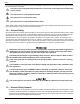
Safety Four commonly used safety symbols accompany the DANGER, WARNING and CAUTION blocks. The type of information each indicates is as follows: * $ ! + This symbol points out important Safety Information that, if not followed, could endanger personal safety and/or property of others. This symbol points out a potential Explosion Hazard. This symbol points out a potential Fire Hazard. This symbol points out a potential Electrical Shock Hazard.
Safety • The engine exhaust fumes contain carbon monoxide, which can be DEADLY. This dangerous gas, if breathed in sufficient concentrations, can cause unconsciousness or even death. DO NOT alter or add to the exhaust system or do anything that might render the system unsafe or in noncompliance with applicable codes and standards. • Install a carbon monoxide alarm indoors, according to manufacturer’s instructions/recommendations.
Safety Health Administration (OSHA) has established. Also, ensure that the generator is installed in accordance with the manufacturer’s instructions and recommendations. Following proper installation, do nothing that might alter a safe installation and render the unit in noncompliance with the aforementioned codes, standards, laws and regulations. • Keep a fire extinguisher near the generator at all times.
Section 2 General Information 2.1 — Synergy Operating Principle 2.1.1— Benefits The Synergy 20 kW generator brings exciting new technology to the Home Standby generator product. The generator is significantly more fuel efficient than constant speed generators at normal loads, provides premium power quality, and is significantly quieter while operating at exercise and normal loads.
General Information 2.1.6— Overload If a load is sensed that is too large for the engine, that load will be locked out for a period of 30 minutes. If the load is not connected through a fast Loadshed enabled controller and module, then the generator shuts down with an “Overload” alarm. 2.1.7— Low Speed Exercise Low speed exercise operates at 1950 RPM for five minutes. The output voltage and frequency will not be at the rated voltage and frequency during exercise. 2.1.
General Information 2.2 — The Generator B D C E F A G H N I J L K M Figure 2-1. Component Locations A. Automatic Voltage Regulator (AVR) H. Circuit Breakers B. Oil Dipstick I. Fuel Inlet (Back) C. Oil Fill Cap J. Fuel Regulator D. Engine Air Filter K. Battery Compartment E. AVR Air Filter L. Oil Filter F. Data Label M. Composite Base G. Control Pad N.
General Information 2.3 — Protection Systems The owner/operator is alerted to Alarm and/or Warning conditions via the control pad LCD screen. All Alarm conditions cause the generator to shut down. The Warning messages alert the operator to conditions that do not disable the unit, require immediate correction, or result in shut down. Some of the possible Alarm/Warning messages are listed below. NOTE: For Synergy specific alarms, see Subsection 5.3 — Synergy Troubleshooting. 2.3.
General Information 2.5 — Specifications 2.5.1— Generator Model 20 kW Synergy Rated Voltage 240 Rated Maximum Load Current (Amps) at 240 Volts (LP)* 83.3 Main Circuit Breaker 90 Amp Phase 1 Rated AC Frequency 60 Hz Battery Requirement Group 26R, 12 Volts and 525 CCA Minimum (Generac Part No. 0H3421S) Unit Weight in Lbs.
General Information 2.5.3— Fuel Requirements The engine has been fitted with a dual fuel carburetion system. The unit will run on natural gas or LP gas (vapor), but it has been factory set to run on natural gas. The fuel system is configured for the selected fuel source during installation. Recommended fuels should have a btu content of at least 1,000 Btus per cubic foot (37.26 megajoules per cubic meter) for natural gas, or at least 2,500 Btus per cubic foot (93.
General Information Table 2-1. Accessories (Continued) Accessory Description Power Management Module (PMM) Starter Kit Includes one module with transformer. The transformer, which is mounted inside the ATS enclosure, interfaces with the OPCB to generate the 24 Vac signal needed for control of the contactor (Load 1 on the OPCB). Power Management Module (PMM) Includes one module only.
General Information This page intentionally left blank.
Section 3 Operation 3.1 — Control Pad * The control pad is intended for use by qualified service personnel only. See Figure 3-1. The control pad is located under the lid of the enclosure. The lid is secured by two locks, one on each side of the enclosure. For best results, press down on the lid directly above the side lock, and while holding the lid down, use key to unlock the latch. Repeat step on opposite side of enclosure.
Operation * With the control pad set to AUTO, the engine may crank and start at any time without warning. Such automatic starting occurs during the programmed exercise cycle or when utility power source voltage drops below the configured level. To prevent possible injury that might occur during sudden starts, always set the control pad to OFF and remove the 7.5 amp fuse before working on or around the generator or transfer switch.
Operation 3.3 — Menu Navigation Feature Description System Menus HOME Screen The system returns to the Home screen if the control pad is not used for five minutes. The screen normally displays a Status message, such as Ready to Run (Auto mode) or Switched to OFF (Off mode), and the total Hours of Protection. If an active alarm/warning condition occurs, the associated Alarm/Warning message is displayed. To clear the Alarm/Warning message, press OFF on the control pad followed by ENTER.
Operation 3.5.2— User Programmable 3.5.2.1—Exercise Time A programmable exercise time is provided. In the AUTO mode, the engine starts and runs at the programmed interval, either weekly, bi-weekly (the default), or monthly, at the time and day specified. During the exercise cycle, the unit runs approximately five minutes and then shuts down. Transfer of loads to the generator does not occur unless utility power fails. For more information, see Subsection 3.12 —Setting the Exercise Timer. 3.
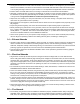
Synergy Automatic Standby Generator Owner’s Manual ESC ESC ESC ESC ESC Å Æ NG or LP Æ Exercise Time 2/12/13 12:22 Æ Å Press Enter Æ Firmware Update 14:00 Wed Weekly Æ Å Current Date/Time Å Fuel Selection English ENTER Å Insert USB Æ Firmware Update ESC - 14 + ENTER ESC ESC ESC - Language ESC ENTER ESC ENTER - 0 + Possible Message(s) Corrupted File Invalid File File Not Found Unsupported Device Quiet Test Mode only on certain models - YES or NO + ESC + Francais - Lang
Operation 3.7 — Transfer Switch Automatic Operation In AUTO, the generator starts automatically when utility source voltage drops below the preset level. Once the unit starts, loads are transferred to the standby power source. To select automatic operation: 1. Verify that the transfer switch main contacts are set to the UTILITY position (loads connected to the utility power source). 2. Verify that normal UTILITY power source voltage is available to transfer switch terminal lugs N1 and N2. 3.
Operation 3.7.2— Load Shed Functionality The Synergy product Transfer Switch includes an Overload Prevention Control Board (OPCB) to shed critical loads. The OPCB, commonly referred to as the Load Shed Board, has “Fast Load Shed” capability, which effectively prevents large loads from stalling the engine. ALL LOADS GREATER THAN 10 kW OR 2 HP (MOTORS) MUST BE CONNECTED TO THE OPCB. If natural gas is the selected fuel type, then all loads greater than 9kW must be connected to the OPCB.
Operation Manual Transfer Handle Load Connected to Utility Load Connected to Standby Transfer Switch Operating Lever Figure 3-4. Manual Transfer Switch Operation (Typical) 6. Turn on the utility power supply to the transfer switch using the means provided. 7. Press AUTO on the control pad. A green LED illuminates to confirm that the system is in the AUTO mode. 3.
Operation 3.10 — Side Door Compartment Check local codes for side door locking requirements. A hasp is provided, so that the side door can be secured with a customer supplied padlock if necessary. LED Indicators 15 Amp Outlet Breaker GFCI BREAKER ON OFF OFF ON ON OFF ON ON OFF OFF GENERATOR DISCONNECT 120 GFCI Outlet Generator Disconnect Circuit Breaker Figure 3-5. Open Side Door Compartment 3.10.
Operation 3.11 — Battery Charger NOTE: The battery charger is integrated into the control module. The battery charger operates as a “Smart Charger” that ensures: • Output is continually optimized to promote maximum battery life. • Charging levels are safe. NOTE: A warning is displayed on the LCD screen when the battery needs service. 3.12 — Setting the Exercise Timer This generator is equipped with a configurable exercise timer. The first of two settings specifies the Day/Time of the exercise.
Section 4 Maintenance 4.1 — Maintenance NOTE: Proper maintenance is necessary for safe operation and is crucial to the life of the generator. Genuine Generac parts MUST be used to ensure warranty coverage NOTE: Since most maintenance alerts occur at the same time (two or four year intervals), only one will appear at any one time. Clearing one will cause the next active alert to be displayed. 4.
Maintenance Table 4-1.
Maintenance 4.5.2— Check Lines and Connections Perform a general inspection as follows: • Check Fuel Lines and Connections for Leaks • Check Oil Lines and Connections for Leaks 4.5.3— Check Engine Oil Level 1. Remove dipstick and wipe with a clean cloth. See A of Figure 4-1. 2. Completely insert the dipstick and then remove it.
Maintenance 4.6 — Schedule A Maintenance NOTE: Perform Schedule A maintenance every two years or after 200 hours of service, whichever comes first. 4.6.1— Check Battery Condition/Fluid Level 4.6.1.1— Check Condition and Clean 1. Remove front access panel. 2. Verify that top of battery is clean and dry. Dirt and electrolyte on top of the battery can cause battery to self-discharge.
Maintenance 4.6.2— Replace AVR Filter + If utility is present, the secondary 12V DC fan continues to operate for up to one hour after the generator is shut down (even if the 7.5 amp ATO fuse is removed). To avoid hand injury, always exercise caution when working near the AVR fan housing. + The AVR remains charged for up to three minutes after power down. To avoid potential electrical shock, allow five minutes to elapse before removing AVR filter housing. 1.
Maintenance 12. Press MANUAL on the control pad to start the engine. A blue LED illuminates to confirm that the system is in the MANUAL mode. 13. Allow the engine to run for a few minutes. Check for leaks while the engine is running. 14. Press OFF on the control pad to shut the engine down. A red LED illuminates to confirm that the system is in the OFF mode. 15. Remove dipstick and wipe with a clean cloth. 16. Completely insert the dipstick and then remove it. 17.
Maintenance 4.7 — Schedule B Maintenance NOTE: Perform Schedule B maintenance every four years or after 400 hours of service, whichever comes first. Before proceeding below, first perform all tasks listed under Schedule A Maintenance. 4.7.1— Replace Engine Air Filter 1. Remove unit from service. See Subsection 4.4 —Remove From Service. 2. Disengage cover clip and remove air cleaner cover. See A of Figure 4-4. 3. Remove air filter and discard. 4.
Maintenance NOTE: When disconnecting spark plug cable from spark plug terminal, always grasp and pull on the boot at the terminal end of the cable. Pulling on cable portion can result in parts damage. 3. Thoroughly clean area around spark plugs. 4. Remove spark plugs from cylinder head using a 5/8 inch spark plug socket. Figure 4-5. Adjust Spark Plug Gap 5. Check condition of threads in cylinder head and on spark plugs.
Maintenance Move piston to Top Dead Center (TDC) of compression stroke (both valves closed). Proceed as follows: 9. a. Remove intake screen at front of engine to gain access to flywheel nut. b. Place large socket and socket wrench on flywheel nut and rotate engine in a clockwise direction while watching piston through spark plug hole. NOTE: Piston is at TDC when it is at the highest point of travel. Left Right 4-Pin Connector Figure 4-6. Remove AVR Fan Connector and Screws 10. Insert a 0.002 - 0.
Maintenance 10. Install the AVR fan. Pivot Ball Stud Jam Nut Rocker Arm Valve Stem Figure 4-7. Check/Adjust Valve Clearance 11. Connect 4-pin connector to AVR. Press pin and socket halves together until external latch engages. 12. Install AVR filter housing so the bottom drops into the slots and ensuring that the rubber boot is completely around the fan opening. Install screw to fasten AVR filter housing to back panel and torque to 50-96 in-lbs (6-11 Nm). 4.8 — Return to Service 1.
Maintenance 2. Allow the unit to warm up for a few minutes. 3. Press OFF on the control pad to stop the engine. A red LED illuminates to confirm that the system is in the OFF mode. 4. While the engine is still warm, completely drain engine oil and refill the crankcase with oil. See Subsection 4.6.3—Replace Engine Oil and Oil Filter. 5. Press MANUAL on the control pad to start the engine. A blue LED illuminates to confirm that the system is in the MANUAL mode. 6.
Maintenance 11. Pull up rubber flap covering fuse holder and install 7.5 amp fuse. 12. Follow Install Wizard instructions using LCD screen and control pad. 13. Press MANUAL on the control pad to start the engine. A blue LED illuminates to confirm that the system is in the MANUAL mode. 14. Allow the unit to warm up for a few minutes. 15. Press OFF on the control pad to stop the engine. A red LED illuminates to confirm that the system is in the OFF mode. 16.
Section 5 Troubleshooting 5.1 — Engine Troubleshooting Table 5-1. Engine Diagnostics Problem Engine will not crank. Cause Correction 1) Fuse blown. 1) Correct short circuit condition by replacing 7.5 Amp fuse. 2) Loose, corroded or defective battery cables. 3) Defective starter contact. 4) Defective starter motor. 5) Dead Battery. 2) Tighten, clean or replace as necessary.* Engine cranks but will not start. 1) Out of fuel. 2) Defective fuel solenoid (FS). 3) Defective spark plug(s).
Troubleshooting 5.2 — Generator Troubleshooting Table 5-2. Generator Diagnostics Active Alarm NONE LED GREEN Problem Things to Check Solution Unit running in AUTO but no power in house. Check Generator Disconnect circuit breaker. Contact servicing dealer if Generator Disconnect circuit breaker is in the ON position. HIGH TEMPERATURE RED Unit shuts down during operation. Check the LEDs/Screen for alarms. Check ventilation around the intake, exhaust and rear of generator.
Troubleshooting Table 5-2. Generator Diagnostics (Continued) Active Alarm LED Problem Things to Check Solution STEPPER OVERCURRENT RED Unit will not start in AUTO with utility loss. Check the LEDs/Screen for alarms. Contact servicing dealer. MISWIRE RED Unit will not start in AUTO with utility loss. Check the LEDs/Screen for alarms. Contact servicing dealer. OVERVOLTAGE RED Unit will not start in AUTO with utility loss. Check the LEDs/Screen for alarms. Contact servicing dealer.
Troubleshooting 5.3 — Synergy Troubleshooting Table 5-3. Synergy Diagnostics Ecode/Active Alarm LED 1048 VSCF Overload RED Unit shuts down during operation. Check the LEDs/Screen for alarms. Alternator, AVR or wiring is damaged. Contact servicing dealer. 1049 VSCF Overload RED Unit shuts down during operation. Check the LEDs/Screen for alarms. Generator output is shorted or severely overloaded. Identify and clear the overload, and then restart. Yellow LED illumi- Check the nated in any state.
Troubleshooting Table 5-3. Synergy Diagnostics (Continued) Ecode/Active Alarm LED Problem Things to Check Possible Causes/Solution 1057 VSCF Overvoltage RED Unit shuts down during operation or starting. Check the LEDs/Screen for alarms. Probable causes are: 1) The generator has been overloaded. Remove load and attempt to restart unit. 2) Generator has started into a severe load. Manually operate transfer switch back to utility position and try to restart unit.
Troubleshooting 5.4 — Load Shed Troubleshooting Table 5-4. Load Shed Diagnostics Symptom Possible Causes Generator stalls when large load is supplied. 1) Total load is too big for the generator and fuel type. Contact installing dealer to correct installation. 2) A large load is not wired through the Loadshed module. Contact installing dealer to correct installation. Large loads keep getting shed and locked out (load LED goes out for 30 minutes). Total load is too big for generator.
Part No. 0K2502 Rev. C 01/20/2015 Printed in USA © Generac Power Systems, Inc. All rights reserved Specifications are subject to change without notice. No reproduction allowed in any form without prior written consent from Generac Power Systems, Inc. Generac Power Systems, Inc. S45 W29290 Hwy. 59 Waukesha, WI 53189 1-888-GENERAC (1-888-436-3722) generac.