Instruction Manual Wireless Local Monitor Model: 006664-0 NOTE: This display unit and it's generator transceiver are a matched pair. The included display unit will only function with the included generator transceiver. www.generac.
Table of Contents TABLE OF CONTENTS SAFETY .......................................................................................................................... 1 Read This Manual Thoroughly ................................................................................... 2 Safety Rules ............................................................................................................... 3 Operation and Maintenance ............................................................................
Safety SAFETY Contains FCC ID: OA3MRF89XAM9A This device complies with Part 15 of the FCC Rules. Operation is subject to the following two conditions: 1. 2. This device may not cause harmful interference, and This device must accept any interference received, including interference that may cause undesired operation. This equipment has been tested and found to comply with the limits for a Class B digital device, pursuant to Part 15 of the FCC rules.
Safety Rules THESE INSTRUCTIONS – This manual is in addition to the Owner's Manual for the generator. All warnings and recommendations SAVE in the manufacturer's manuals must be strictly adhered to for safe use. THESE INSTRUCTIONS – The manufacturer suggests that these SAVE rules for safe operation be copied and posted in potential hazard areas. Safety should be stressed to all operators, potential operators, and service and repair technicians for this equipment.
Safety Rules Four commonly used safety symbols accompany the DANGER, WARNING and CAUTION blocks. The type of information each indicates is as follows: symbol points out important safety information that, if not This followed, could endanger personal safety and/or property of others. This symbol points out potential explosion hazard. This symbol points out potential fire hazard. This symbol points out potential electrical shock hazard.
Safety Rules GENERAL HAZARDS • For safety reasons, the manufacturer recommends that the installation, initial start-up and maintenance of this equipment is carried out by a Dealer. • Keep hands, feet, clothing, etc., away from drive belts, fans, and other moving or hot parts. Never remove any drive belt or fan guard while the unit is operating. • When working on this equipment, remain alert at all times. Never work on the equipment when physically or mentally fatigued.
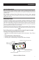
Introduction HOW TO OBTAIN SERVICE When the generator requires servicing or repairs, contact an Authorized Service Dealer for assistance. Service technicians are factory-trained and are capable of handling all service needs (1-800-333-1322). When contacting an Authorized Service Dealer about parts and service, always supply the complete model number of the unit as given on the front cover of this manual or on the DATA LABEL affixed to the unit.
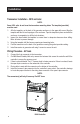
Installation GENERATOR COMPATIBILITY • This unit can be installed on all 2008 and later air-cooled home standby units with an LCD display and all 2010 and later liquid-cooled gaseous fuel standby units. The unit can also be used on 2013 and later Evolution controlled liquid-cooled diesel fuel standby units. • Certain liquid-cooled units require the use of adapter harness (model 006665-0). These units are as follows: - All Protector Series and QT generators that do not have a pre-stamped mounting location.
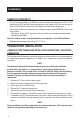
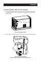
Installation Transceiver Installation - 2008 - 2012 with LCD Display 1. Locate the mounting feature and cover plate on the back of the generator. Remove the cover plate, then position transceiver on the back of the generator ensuring the gasket provides sealing. MOUNTING LOCATION Transceiver Mounting Location 2. Install 2 screws from inside the generator to secure the transceiver to the generator wall.
Installation Transceiver Installation - 2013 and Later NOTE: Some 2013 units do not have the transceiver mounting holes. The template (provided) must be used. 1. 3. 4. Affix the template, on the back of the generator enclosure, in the upper left corner. Align the template with the left and top edges of the enclosure. Tape the template in place and mark the enclosure, in preparation to drill the hole locations. Inspect the area behind the template to ensure there is adequate clearance when drilling.
Installation 2010 Controller 2013 Controller 9
Installation Final Installation - All Years 1. 2. 3. 4. 5. 6. 7. 8. Reconnect the positive (+) red battery cable first. Then, reconnect the negative (-) black cable. Install the controller and cover. Secure with fasteners (2008 Home Standby Units only). Reinstall the generator front access panel. Install the 7.5 Amp control panel fuse. Reinstall the T1 fuse into the transfer switch. If applicable, turn ON the home's electrical panel main breaker. Place the generator in the AUTO mode.
Installation SIGNAL STRENGTH TEST QUICK REFERENCE CHART Signal Strength Test is active - Display unit button must be pressed for more than 5 seconds Display unit lights will go from providing current generator status to a rotating light pattern to signal a change in function to a Signal Strength Test Mode. It will repeat the rotating light pattern when it exits Signal Strength Test Mode. Green Light Yellow Light Red Light Meaning ON OFF OFF Strong signal from Transceiver unit to Display unit.
Operation WIRELESS LOCAL MONITOR GENERAL OPERATION The normal state of the display unit is to have no lights active. This indicates that the generator has no problems. When any problems occur, the lights will indicate the problem based on the information in this section. GENERATOR TRANSCEIVER STATUS LIGHT The generator transceiver has a green status light that indicates it has power and is communicating with the display unit.
Operation DISPLAY UNIT RED LIGHT (CHECK GENERATOR STATUS, CALL DEALER IF NECESSARY) The red light indicates either: • The AUTO/OFF/MANUAL button on the generator is in the OFF mode • A generator alarm is present. If a generator alarm is present, the generator will not start and run in the event of a utility loss or will be automatically shut down if the engine is already running. When active, the red light will flash once every five (5) seconds.
Troubleshooting TROUBLESHOOTING Problem Possible Causes Possible Corrective Actions The transceiver is not receiving power. Check that the harness transceiver Connection to generator transceiver connection is made properly at the may not be made. transceiver and controller. Generator transceiver light not illuminated The transceiver is not receiving power. Check and replace fuse. Fuse has failed, been damaged or is removed from generator controller. The transceiver is not receiving power.
Quick Reference Chart QUICK REFERENCE CHART Green Light Yellow Light Red Light Battery Status Indicator Buzzer Meaning — — — Flash every 5 seconds 1 second every 15 minutes Replace batteries in Display unit. Remove batteries to silence buzzer. OFF OFF Flash every 5 seconds Flash every 5 seconds Flash every 5 seconds OFF — Generator will not run. Alarm condition reported. Press 5 seconds Test button to silence buzzer. every hour Buzzer will re-activate with new warning.
Notes 16
Warranty GENERAC POWER SYSTEMS “ONE YEAR” LIMITED WARRANTY FOR WIRELESS REMOTE MONITOR (FOR RESIDENTIAL/COMMERCIAL GENERATORS) For a period of one (1) year from the date of original sale, Generac Power Systems, Inc. (Generac) warrants its wireless remote monitor will be free from defects in materials and workmanship for the items and period set forth below.
Warranty 12. Freight costs for replacement part(s). 13. Labor charges. THIS WARRANTY IS IN PLACE OF ALL OTHER WARRANTIES, EXPRESSED OR IMPLIED. SPECIFICALLY, GENERAC MAKES NO OTHER WARRANTIES AS TO THE MERCHANTABILITY OR FITNESS FOR A PARTICULAR PURPOSE. Any implied warranties which are allowed by law, shall be limited in duration to the terms of the express warranty provided herein. Some states do not allow limitations on how long an implied warranty lasts, so the above limitation may not apply to you.
Manual de instrucciones Monitor inalámbrico local Modelo: 006664-0 NOTA: Esta unidad de pantalla y su transceptor de generador son un par apareado. La unidad de pantalla incluida solo funcionará con el transceptor de generador incluido. www.generac.
Índice ÍNDICE SEGURIDAD .......................................................................................................................... 1 Lea este manual minuciosamente .................................................................................... 2 Reglas de seguridad ......................................................................................................... 3 Funcionamiento y mantenimiento .....................................................................................
Seguridad SEGURIDAD Contiene identificación de la FCC: OA3MRF89XAM9A Este dispositivo cumple con la Parte 15 de las Reglas de la Comisión Federal de Comunicaciones (FCC) de EE. UU. El funcionamiento está sujeto a las siguientes dos condiciones: 1. 2. Este dispositivo no debe causar interferencia perjudicial, y Este dispositivo debe aceptar cualquier interferencia recibida, incluso la interferencia que podría causar el funcionamiento no deseado.
Reglas de seguridad ESTAS INSTRUCCIONES - Este manual es un agregado al Manual del propietario del generador. Observe estrictamente todas las GUARDE advertencias y recomendaciones del manual del fabricante para un uso seguro. ESTAS INSTRUCCIONES - El fabricante sugiere que estas reglas GUARDE para funcionamiento seguro sean copiadas y expuestas en zonas de peligro potencial.
Reglas de seguridad símbolo señala información de seguridad importante que, si no se respeta, podría poner en peligro la seguridad personal y/o material de Este terceros. Este símbolo señala un posible peligro de incendio. Este símbolo señala un posible peligro de choque eléctrico. Este símbolo señala un posible peligro de explosión. REGLAS DE SEGURIDAD Estudie cuidadosamente estas REGLAS DE SEGURIDAD antes de instalar, operar o efectuar el mantenimiento de este equipo.
Reglas de seguridad PELIGROS ELÉCTRICOS • No maneje ningún tipo de dispositivo eléctrico mientras esté parado sobre agua o esté descalzo o cuando tenga las manos o los pies mojados. PUEDE PRODUCIRSE UN CHOQUE ELÉCTRICO PELIGROSO. En caso de accidente causado por choque eléctrico, apague de inmediato la fuente de alimentación eléctrica. Si esto no es posible, intente liberar a la víctima del conductor alimentado. EVITE EL CONTACTO DIRECTO CON LA VÍCTIMA.
Introducción CÓMO OBTENER SERVICIO Cuando el generador requiera mantenimiento o reparaciones, comuníquese con un concesionario de servicio autorizado para obtener ayuda. Los técnicos de servicio reciben capacitación en la fábrica y tienen capacidad para atender todas las necesidades de servicio (1-800-333-1322).
Instalación COMPATIBILIDAD DEL GENERADOR • Esta unidad se puede instalar en todas las unidades de reserva para hogares enfriadas por aire de 2008 y posteriores, con una pantalla LCD, y en todas las unidades de reserva de combustible gaseoso enfriadas por líquido de 2010 y posteriores. La unidad también se puede usar en las unidades de reserva de combustible diésel enfriadas por líquido con control Evolution de 2013 y posteriores.
Instalación Instalación del transceptor - 2008 - 2012 con pantalla LCD. 1. Ubique el dispositivo de montaje y la placa de cubierta en la parte trasera del generador. Retire la placa de cubierta, luego coloque el transceptor en posición en la parte trasera del generador asegurando que la junta selle. UBICACIÓN DE MONTAJE Ubicación de montaje del transceptor 2. Instale 2 tornillos desde el interior del generador para fijar el transceptor en la pared del generador.
Instalación Instalación del transceptor - 2013 y posteriores NOTA: Algunas de las unidades de 2013 no tienen agujeros de montaje para el transceptor. Se debe usar la plantilla (provista). 1. 3. 4. Coloque la plantilla, en la parte trasera del gabinete del generador, en la esquina superior derecha. Alinee la plantilla con los bordes izquierdo y superior del gabinete. Sujete la plantilla con cinta en su lugar y marque el gabinete como preparación para perforar los agujeros en los lugares correspondientes.
Instalación Controlador 2010 Controlador 2013 9
Instalación Instalación final - Todos los años 1. 2. 3. 4. 5. 6. 7. 8. Vuelva a conectar el cable positivo (+) rojo de la batería primero. Luego, vuelva a conectar el cable negativo (-) negro. Instale el controlador y la cubierta. Sujete con sujetadores (solamente unidades de reserva para hogares de 2008). Vuelva a instalar el panel de acceso delantero del generador. Instale el fusible de 7.5 A del tablero de control. Vuelva a instalar el fusible T1 en el interruptor de transferencia.
Instalación TABLA DE REFERENCIA RÁPIDA PARA LA PRUEBA DE INTENSIDAD DE LA SEÑAL La prueba de intensidad de la señal está activa - Se debe pulsar el botón de la unidad de pantalla durante más de 5 segundos - Las luces de la unidad pasarán de presentar el estado actual del generador a un patrón de luces alternado para señalar un cambio de función al Modo de prueba de intensidad de la señal. Repetirá el patrón de luces alternado cuando salga del Modo de prueba de intensidad de la señal.
Funcionamiento FUNCIONAMIENTO GENERAL DEL MONITOR INALÁMBRICO LOCAL En el estado normal, la unidad de pantalla no tendrá ninguna luz activa. Esto indica que el generador no tiene ningún problema. Cuando sucede algún problema, las luces indicarán el problema conforme a la información dada en esta sección. LUZ DE ESTADO DEL TRANSCEPTOR DE GENERADOR El transceptor de generador tiene una luz de estado verde que indica que recibe alimentación y que se está comunicando con la unidad de pantalla.
Funcionamiento LUZ ROJA DE LA UNIDAD DE PANTALLA (COMPROBAR EL ESTADO DEL GENERADOR, LLAMAR AL CONCESIONARIO SI ES NECESARIO) La luz roja indica uno de las siguientes condiciones: • El botón AUTO/OFF/MANUAL del generador está en el modo OFF. • Hay presente una alarma del generador. Si hay una alarma del generador presente, el generador no arrancará o funcionará en caso de pérdida de servicio público, o parará automáticamente si el motor ya se encuentra funcionando.
Resolución de problemas RESOLUCIÓN DE PROBLEMAS Problema Causas posibles El transceptor no está recibiendo alimentación. Puede no haberse efectuado la conexión del transceptor de generador. La luz del transceptor El transceptor no está recibiendo de generador no está alimentación. El fusible ha fallado, está dañado o se ha retirado el controlador encendida del generador. El transceptor no está recibiendo alimentación. La batería del generador está desconectada.
Tabla de referencia rápida TABLA DE REFERENCIA RÁPIDA Luz verde Luz amarilla Luz roja Indicador de estado de la batería — — — Destello cada 5 segundos OFF OFF Destello cada 5 segundos — Destello Destello cada cada 5 segundos 5 segundos OFF — OFF Destello cada 5 segundos OFF — OFF Destello Destello cada cada 5 segundos 5 segundos — Chicharra Sustituya las baterías de la unidad de pantalla. Retire las baterías para silenciar la chicharra. El generador no funcionará.
Notas 16
Garantía GARANTÍA LIMITADA DE "UN AÑO" DE GENERAC POWER SYSTEMS PARA MONITORES REMOTOS INALÁMBRICOS (PARA GENERADORES RESIDENCIALES/COMERCIALES) Durante un período de un (1) año desde la fecha de venta original, Generac Power Systems, Inc. (Generac) garantiza que sus monitores remotos inalámbricos estarán libres de defectos de materiales y mano de obra para los ítems y el período indicados a continuación.
Garantía 10. Gastos de estadía o viaje de la(s) persona(s) que efectúe(n) el servicio, excepto como se incluya específicamente dentro de los términos del período de garantía de una unidad específica. 11. Equipos arrendados usados mientras se estaban efectuando reparaciones de garantía. 12. Costes de flete para la(s) pieza(s) de repuesto. 13. Cargos de mano de obra. ESTA GARANTÍA SUSTITUYE CUALQUIER OTRA GARANTÍA, EXPRESA O IMPLÍCITA.
Mode d’emploi Moniteur local sans fil Modèle : 006664-0 REMARQUE : Ce dispositif d’affichage et son émetteur-récepteur pour générateur sont une paire assortie. Le dispositif d’affichage inclus fonctionnera seulement avec l’émetteurrécepteur pour générateur inclus. www.generac.
Table des matières TABLE DES MATIÈRES SÉCURITÉ ..........................................................................................................................1 Lire ce manuel attentivement .........................................................................................2 Règles de sécurité..........................................................................................................3 Fonctionnement et entretien ..................................................................
Sécurité SÉCURITÉ Comprend l’identification FCC : OA3MRF89XAM9A Cet appareil est conforme à la partie 15 des règlements de la FCC. Le fonctionnement de l’appareil est assujetti aux deux conditions suivantes : 1. 2. Cet appareil ne peut pas causer d’interférences nuisibles. Cet appareil doit accepter toute interférence reçue, y compris les interférences qui peuvent être la cause d’un fonctionnement non souhaité.
Règles de sécurité CES INSTRUCTIONS - Ce manuel est complémentaire au Manuel du propriétaire du générateur. Tous les avertissements et les CONSERVEZ recommandations contenus dans le manuel du fabricant doivent être respectés pour un usage sécuritaire. CONSERVEZ CES INSTRUCTIONS - Le fabricant suggère que ces règles de fonctionnement sécuritaire soient copiées et affichées dans les zones où des dangers potentiels sont présents.
Règles de sécurité symbole fournit des informations de sécurité importantes qui, si elles ne sont pas suivies, pourraient mettre en danger la sécurité des Ce personnes ou les biens d’autrui. Ce symbole indique un risque potentiel d’incendie. Ce symbole indique un risque potentiel de décharge électrique. Ce symbole indique un risque potentiel d’explosion. RÈGLES DE SÉCURITÉ Étudiez ces RÈGLES DE SÉCURITÉ avant l’installation, l’utilisation ou l’entretien de cet équipement.
Règles de sécurité RISQUES ÉLECTRIQUES • Ne touchez jamais un appareil électrique lorsque vous êtes debout sur un sol mouillé, pieds nus ou lorsque vos mains ou vos pieds sont humides. UNE DÉCHARGE ÉLECTRIQUE DANGEREUSE PEUT SE PRODUIRE. • En cas d’accident causé par une décharge électrique, coupez immédiatement la source d’énergie électrique. Si cela n’est pas possible, essayez de libérer la victime du conducteur sous tension. ÉVITEZ TOUT CONTACT DIRECT AVEC LA VICTIME.
Introduction COMMENT OBTENIR DES SERVICES Lorsque le générateur requiert un entretien ou une réparation, veuillez communiquer avec un fournisseur de services d’entretien agréé pour de l’assistance. Les techniciens d’entretien sont formés à l’usine et peuvent effectuer tous les services d’entretien (1-800-333-1322).
Installation COMPATIBILITÉ DU GÉNÉRATEUR • Cet appareil peut être installé sur tous les générateurs de secours résidentiels refroidis à l’air de 2008 ou plus récents munis d’un écran ACL et sur tous les générateurs de secours à carburant gazeux refroidis par liquide de 2010 ou plus récents. L’appareil peut aussi être utilisé avec les générateurs de secours à carburant diesel refroidis à l’air contrôlé Evolution de 2013 ou plus récents.
Installation Installation de l’émetteur-récepteur - 2008 à 2012 avec affichage ACL 1. Trouvez les caractéristiques de montage et la plaque de recouvrement qui se trouvent à l’arrière du générateur. Enlevez la plaque de recouvrement et positionnez l’émetteur-récepteur à l’arrière du générateur en vous assurant que le joint fournisse une étanchéité adéquate. EMPLACEMENT DE MONTAGE Emplacement de montage de l’émetteur-récepteur 2.
Installation Installation de l’émetteur-récepteur - 2013 et plus récent REMARQUE : Certains des appareils de 2013 ne possèdent pas de trous de montage pour l’émetteurrécepteur. Le gabarit (fourni) doit être utilisé. 1. 2. 3. 4. 5. Posez le gabarit à l’arrière du boîtier du générateur dans le coin supérieur gauche. Alignez le gabarit avec le bord gauche et le bord supérieur du boîtier.
Installation Régulateur 2010 Régulateur 2013 9
Installation Installation finale - Toutes les années 1. 2. 3. 4. 5. 6. 7. 8. Rebranchez le câble de batterie rouge positif (+) en premier. Rebranchez ensuite le câble noir négatif (-). Installez le régulateur et le couvercle. Fixez à l’aide d’attaches (appareils de secours résidentiels de 2008 seulement). Réinstallez le panneau d’accès frontal du générateur. Installez le fusible de 7,5 A du tableau de commande. Réinstallez le fusible T1 dans le commutateur de transfert.
Installation TABLEAU DE RÉFÉRENCE RAPIDE DE L’ESSAI POUR L’INTENSITÉ DU SIGNAL L’essai pour l’intensité du signal est actif - Le bouton de l’appareil d’affichage doit être maintenu enfoncé durant plus de 5 secondes - Les voyants de l’appareil d’affichage passeront de l’indication de l’état actuel du générateur à une série rotative pour signaler un changement de fonction et le passage en mode d’essai pour l’intensité du signal.
Fonctionnement FONCTIONNEMENT GÉNÉRAL DU MONITEUR LOCAL SANS FIL L’état normal de l’appareil d’affichage est lorsqu’aucun voyant n’est actif. Cela indique qu’il n’y a aucun problème avec le générateur. Lorsqu’un problème se produit, les voyants indiqueront le problème selon l’information contenue dans cette section.
Fonctionnement VOYANT ROUGE DE L’APPAREIL D’AFFICHAGE (VÉRIFIEZ L’ÉTAT DU GÉNÉRATEUR, APPELEZ UN FOURNISSEUR SI NÉCESSAIRE) Le voyant rouge indique : • Que le bouton AUTO/ARRÊT/MANUEL du générateur est en mode ARRÊT • Qu’une alarme pour le générateur est présente. Si une alarme est présente, le générateur ne démarrera pas et ne fonctionnera pas si une panne du réseau public se produit ou s’éteindra automatiquement si le moteur est déjà en marche.
Dépannage DÉPANNAGE Problème Causes possibles L’émetteur-récepteur n’est pas alimenté. Il est possible qu’il n’y ait pas de connexion avec l’émetteur-récepteur du générateur. Le voyant de l’émetteur- L’émetteur-récepteur n’est pas alimenté. Le fusible a sauté, a été récepteur n’est pas endommagé ou a été enlevé du allumé. régulateur du générateur. L’émetteur-récepteur n’est pas alimenté. La batterie du générateur est déconnectée.
Tableau de référence rapide TABLEAU DE RÉFÉRENCE RAPIDE Voyant vert Voyant jaune Voyant rouge Indicateur de Avertisseur l’état de la pile 1 seconde toutes les 15 minutes - - - Clignote toutes les 5 secondes. ARRÊT ARRÊT Clignote toutes les 5 secondes. - 5 secondes toutes les heures Clignote Clignote toutes toutes les 5 les 5 secondes. secondes. ARRÊT - 1 seconde toutes les 4 heures ARRÊT Clignote toutes les 5 secondes.
Remarques 16
Garantie GARANTIE LIMITÉE D'« UN AN » DE GENERAC POWER SYSTEMS POUR LE MONITEUR À DISTANCE SANS FIL (POUR LES GÉNÉRATEURS RÉSIDENTIELS ET COMMERCIAUX) La société Generac Power Systems, Inc. (ci-après dénommée « Generac ») garantit que, pendant une période d'une année à compter de la date d'achat d'origine, ses moniteurs à distance sans fil ne présenteront aucun défaut de matériel ni de fabrication pour les éléments et les périodes mentionnées ci-après.
Garantie 8. 9. 10. 11. 12. 13. Les défaillances dues à une application incorrecte. Frais de téléphone, de télégramme, de téléscripteur ou de tout autre moyen de communication. Les frais d'hébergement ou de transport de la ou des personnes réalisant l'entretien, sauf s'ils sont spécifiquement inclus en vertu des conditions d'une période de garantie d'une unité spécifique. La location de l'équipement utilisé pendant que les réparations sous garantie sont effectuées.