
Install Manual


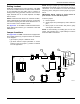
Table Of Contents

General Information and Setup
4 Owner’s/Installation Manual for SMM
SMM and Carton Contents
Priority Dial (A)—Sets module priority.
NOTE: PRIORITY MUST BE DIFFERENT for each
module in an installation. Priority sets the order in
which loads recover from a load shed event. Recovery
time from a load shed event is five minutes for Priority 1.
Each priority after Priority 1 waits an additional 15 sec-
onds after the initial recovery time. See Table 2-1.
Lockout Switch (B)—Enables or disables lockout
function. Switch positions are LOCKOUT LOAD ON
GENERATOR (enabled) and LOCKOUT DISABLED.
See Table 2-2.
NOTE: Recovery time is based on priority dial settings.
See Table 2-1.
Test Button (C)—Disables contactor output for a
specified time.
LED (D)—Provides module status. See Table 2-3.
Contactor (E)—Normally OPEN. If generator begins to
overload, the contactor opens to take load off generator
power. See Connections .
Mounting Holes (F)—Internal enclosure mounting holes
provide clean and sturdy mounting.
Directional Arrows (G)—Provided for mounting
purposes.
Priority Decal (H)—Provided for recording priority of
each module in installation. Install on electrical panel.
Figure 2-1. SMM Features and Controls
A
B C D
E
F
F
H
009380
G