
Full Product Manual

Operation
12 Owner’s Manual for 60 Hz Air-Cooled Generators
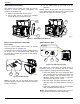
Intake Side Panel Removal
See Figure 3-2. The intake side panel (A) must be
removed to access the battery compartment, fuel
regulator, and sediment trap.
1. Raise the lid and remove the front panel.
2. Use an Allen wrench to remove two mounting
screws (B) and the L-bracket screw (C).
3. Lift the intake panel up and away from the
generator.
NOTE: Always lift the intake side panel straight up
before pulling away from enclosure. Do not pull the panel
away from the enclosure before lifting up (D).
Figure 3-2. Intake Side Panel Removal
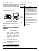
Main Line Circuit Breaker (Generator
Disconnect)
This is a 2-pole breaker rated according to relevant
specifications. See “A” in Figure 3-3.
The breaker can be locked in the OFF (OPEN) position
for security. Use an appropriately-sized padlock (not
included) with a shackle long enough to pass through
both lock tabs (B).
Figure 3-3. Main Breaker
NOTE: DO NOT lock out the MLCB during normal
generator operation. Doing so will compromise automatic
standby functionality.
LED Indicator Lights
Figure 3-4. LED Indicator Lights
See Figure 3-4. Three LEDs are visible behind a
translucent lens on the generator side panel. These
LEDs indicate the operating status of the generator.
• Green LED “Ready” light (A) is illuminated when
utility is present and the control panel button is in
the AUTO position. The LED flashes when the
automatic transfer switch converts to generator
power during a utility power outage.
• Red LED “Alarm” light (B) is illuminated when the
generator is OFF or a fault is detected. Contact an
IASD.
• Yellow LED “Maintenance” light (C) is illuminated
when scheduled maintenance is due.
NOTE: Yellow Maintenance or Warning LED may be on
at the same time as either the Red or Green LED.
002961
A
B
D
C
001810
B
A
001791
B
C
A