® Installation Guidelines 60 Hz Air-Cooled Generators 15kW EcoGen™ WARNING Loss of life. This product is not intended to be used in a critical life support application. Failure to adhere to this warning could result in death or serious injury. (000209b) Register your Generac product at: WWW.GENERAC.COM 1-888-GENERAC (888-436-3722) Para español, visita: http://www.generac.com/service-support/product-support-lookup Pour le français, visiter : http://www.generac.
Use this page to record important information about this generator. Record the information found on the unit data label on this page. For the location of the unit data label, see owner’s Model: manual. The unit has a label plate affixed to the inside partition, to the left of the control panel console. Serial: Always supply the complete model and serial numbers of the unit when contacting an Independent Authorized Service Dealer (IASD) about parts and service.
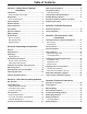
Table of Contents Section 1: Safety Rules & General Information Introduction ..................................................................1 Read This Manual Thoroughly ....................................1 Safety Rules .................................................................1 How to Obtain Service .................................................2 General Hazards ...........................................................2 Water Ingress Avoidance ..........................................
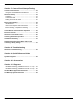
Section 7: Control Panel Startup/Testing Control Panel Interface ............................................. 33 Using the AUTO/MANUAL/OFF Buttons ................. 33 Generator Setup ........................................................ 33 Activation .................................................................. 33 Cold Smart Start ....................................................... 35 Setting The Exercise Timer ....................................... 35 Before Initial Startup .................
Safety Rules & General Information Section 1: Safety Rules & General Information Introduction Thank you for purchasing this compact, high performance, air-cooled, engine-driven generator. In off-grid applications as part of an alternative energy system, the generator starts when the inverter or battery charger detects the normal power source voltage has dropped below a preset level. The generator powers the inverter and, once battery voltage rises to an acceptable level, the generator shuts down.
Safety Rules & General Information How to Obtain Service When the unit requires servicing or repairs, contact Generac Customer Service at 1-888-GENERAC (1-888-4363722) or visit www.generac.com for assistance. When contacting Generac Customer Service about parts and service, always supply the complete model and serial number of the unit as given on its data decal located on the unit. Record the model and serial numbers in the spaces provided on the front cover of this manual.
Safety Rules & General Information DANGER WARNING Injury and equipment damage. Do not use generator as a step. Doing so could result in falling, damaged parts, unsafe equipment operation, and could result in death or serious injury. (000216) Electrical backfeed. Use only approved switchgear to isolate generator from the normal power source. Failure to do so will result in death, serious injury, and equipment damage.
Safety Rules & General Information DANGER WARNING Fire and explosion. Installation must comply with all local, state, and national electrical building codes. Noncompliance could result in unsafe operation, equipment damage, death or serious injury. (000218) WARNING Risk of fire. Allow fuel spills to completely dry before starting engine. Failure to do so will result in death or serious injury. (000174) WARNING Fire hazard. Use only fully-charged fire extinguishers rated “ABC” by the NFPA.
Safety Rules & General Information WARNING WARNING Risk of burn. Do not open or mutilate batteries. Batteries contain electrolyte solution which can cause burns and blindness. If electrolyte contacts skin or eyes, flush with water and seek immediate (000163a) medical attention. Consult Manual. Read and understand manual completely before using product. Failure to completely understand manual and product could result in death or serious injury.
Safety Rules & General Information Standards Index WARNING Loss of life. This product is not intended to be used in a critical life support application. Failure to adhere to this warning could result in death or serious injury. (000209b) * www.nfpa.org ** www.iccsafe.org *** www.rerc.org Rural Electricity Resource Council P.O. Box 309 Wilmington, OH 45177-0309 **** www.asabe.org American Society of Agricultural & Biological Engineers 2950 Niles Road, St.
Unpacking and Inspection Section 2: Unpacking and Inspection General NOTE: Carefully inspect contents for damage after unpacking. Unpack and inspect unit immediately upon delivery to identify any damage which may have occurred in transit. Any claims for shipping damage need to be filed as soon as possible with the freight carrier. This is especially important if the unit will not be installed for a period of time. Unpacking 1. Remove outer shipping carton. 2. See Figure 2-1. Remove wood frame.
Unpacking and Inspection IMPORTANT NOTE: DO NOT perform next step until generator has been transported to installation site. 4. See Figure 2-3. Remove bolts and pallet brackets (A). Exercise caution when removing generator. Dragging it off pallet will damage base. The unit must be lifted from wooden pallet to remove. NOTE: Bolts and pallet brackets are provided only for shipping purposes and can be discarded after removal.
Unpacking and Inspection Intake Side Panel Removal See Figure 2-6. The intake side panel (A) must be removed to access battery compartment, fuel regulator, and sediment trap. 1. Raise lid and remove front panel. 2. Use a hex key to remove two mounting screws (B) and the hex screw on the L-bracket. 3. Lift intake panel up and away from generator. 4. Inspect for any hidden freight damage. Contact freight carrier if damage is present.
Unpacking and Inspection Generator Main Line Circuit Breaker Parts Shipped Loose See Figure 2-9. The 2-pole circuit breaker (generator disconnect) (A) is rated according to relevant specifications. F E B D C A 003599 B A 001810 Figure 2-9. Generator Main Line Circuit Breaker Breaker can be locked in OFF (OPEN) position for security during maintenance or transfer switch service. Use an appropriately-sized padlock (not included) with a shackle long enough to pass through both lock tabs (B).
Unpacking and Inspection Auxiliary Shutdown Switch CAUTION Equipment Damage. The auxiliary shutdown switch is not to be used to power down the unit under normal operating circumstances. Doing so will result in equipment damage. (000399) All generators are equipped with an external means of shutting down the generator which complies with the latest NEC code requirement. The primary generator shutdown sequence is described in Control Panel Startup/ Testing. See Figure 2-11.
Unpacking and Inspection This page intentionally left blank.
Site Selection and Preparation Section 3: Site Selection and Preparation Site Selection Site selection is critical for safe generator operation. It is important to discuss these factors with the installer when selecting a site for generator installation: • • • • • • Carbon monoxide Fire prevention Fresh air for ventilation and cooling Water ingress prevention Proximity to utilities Suitable mounting surface The following pages describe each of these factors in detail.
Site Selection and Preparation Potential CO Entry Points Protect the Structure See Figure 3-1. Generator exhaust can enter a structure through large openings, such as windows and doors. However, exhaust and CO can also seep into the structure through smaller, less obvious openings. Verify structure itself is correctly caulked and sealed to prevent air from leaking in or out. Voids, cracks, or openings around windows, doors, soffits, pipes, and vents can allow exhaust gas to be drawn into the structure.
Site Selection and Preparation Fire Prevention The generator must be installed at a safe distance away from combustible materials. Engine, alternator, and exhaust system components become very hot during operation. Fire risk increases if unit is not correctly ventilated, is not correctly maintained, operates too close to combustible materials, or if fuel leaks exist. Also, accumulations of flammable debris within or outside the generator enclosure may ignite. Distance Requirements See Figure 3-2.
Site Selection and Preparation Fire Codes, Standards, and Guidelines Generator installation must comply strictly with ICC IFGC, NFPA 37, NFPA 54, NFPA 58, and NFPA 70 standards. These standards prescribe the minimum safe clearances around and above the generator enclosure. NFPA 37 NFPA 37 is the The National Fire Protection Association’s standard for the installation and use of stationary combustion engines.
Site Selection and Preparation Fresh Air for Ventilation and Cooling Suitable Mounting Surface Install unit where air inlet and outlet openings will not become obstructed by leaves, grass, snow, etc. If prevailing winds will cause blowing or drifting, consider using a windbreak at a safe distance to protect the unit. See Figure 3-4. Prepare a rectangular area approximately 5 in (127 mm) deep (A) and approximately 3 in (76.2 mm) longer and wider (B) than the generator on all sides.
Site Selection and Preparation This page intentionally left blank.
Generator Placement Section 4: Generator Placement Generator Placement See Figure 4-1. All air-cooled generators come with a composite pad. The composite pad elevates the generator and helps prevent water from pooling around base. Three 3/8 in (or M10) lag bolts (not supplied) are recommended for securing the generator to a concrete pad. NOTE: The top of the generator carton has a template which can be used to mark the concrete pad to pre-drill the mounting holes. Fascia Installation 000612 1.
Generator Placement This page intentionally left blank.
Fuel Conversion / Gas Connections Section 5: Fuel Conversion / Gas Connections Fuel Requirements and Recommendations Piping strength and connections should be given special consideration for installations in areas at risk for flooding, tornadoes, hurricanes, earthquakes, and unstable ground. DANGER Explosion and fire. Fuel and vapors are extremely flammable and explosive. No leakage of fuel is permitted. Keep fire and spark away. Failure to do so will result in death or serious injury.
Fuel Conversion / Gas Connections Fuel Consumption Generator 15 kW Natural Gas Propane 1/2 Load Full Load 1/2 Load Full Load 5.52 / 195 7.87 / 278 1.84 / 6.95 / 66.8 2.76 / 10.45 / 100 * Natural gas is in m3/h / ft3/h ** Propane is in gal/h (LP) / L/h (LP) / ft3/h (LPV) *** Values given are approximate These are approximate values. Use the appropriate spec sheet or fuel data decal for specific values.
Fuel Conversion / Gas Connections Natural Gas Pipe Sizing To determine correct NG pipe size, find the kW rating of generator in the left column, and trace to the right. The number to the right is maximum length (measured in ft / m) allowed for the pipe sizes on top. Pipe sizes are measured by trade size diameter to include any fittings, valves (must be full flow), elbows, tees, or angles. NOTE: See Table B.3.2 in NFPA 54 or Table A.2.
Fuel Conversion / Gas Connections Installing and Connecting Fuel Lines . DANGER Explosion and fire. Fuel and vapors are extremely flammable and explosive. No leakage of fuel is permitted. Keep fire and spark away. Failure to do so will result in death or serious injury. (000192) IMPORTANT NOTE: NG and LP gas are highly volatile substances. Strictly adhere to all safety procedures, codes, standards, and regulations.
Fuel Conversion / Gas Connections Checking Fuel Line Connections Performing Fuel System Leak Test Checking Fuel Pressure Proceed as follows to check fuel pressure at the regulator in the generator: 1. Close fuel supply valve. 2. See Figure 5-4. Remove top fuel pressure test port from regulator and install fuel pressure tester (manometer). 3. Open fuel supply valve and verify fuel pressure is within specified values. 4.
Fuel Conversion / Gas Connections Natural Gas Installation (Typical) A D F E I C B G H J 008965 NG BTU/h = ft3/h X 1000 Megajoules/h = m3/h X 37.26 A Fuel data decal B Minimum distance from rear obstruction—see Distance Requirements C Manual fuel shutoff valve (pressure port optional) Must be located no more than 6 ft (1.
Fuel Conversion / Gas Connections LP Gas (Vapor) Installation (Typical) A D E J L H G K C B F 008966 LPG BTU/h = ft3/h X 2500 Megajoules/h = m3/h X 93.15 A Fuel data decal B Minimum distance from rear obstruction—see Distance Requirements C Manual fuel shutoff valve (pressure port optional) Must be located no more than 6 ft (1.83 m) away from fuel inlet.
Fuel Conversion / Gas Connections This page intentionally left blank.
Electrical Connections Section 6: Electrical Connections Generator Connections See Figure 6-1. The electrical wiring enclosure is located behind an access panel on the intake end of the unit. Remove intake side panel as directed in Intake Side Panel Removal, and then remove access panel. Connect wires according to diagram and tables. 1. Remove main AC / control wiring knock-out plugs from back of generator. 2.
Electrical Connections Control Wiring B A C1 1 1 1 0 1 DC GROUND 2 194 2 2 0 2 194 1 1 2 N2 3 23 3TRANSFER E1 1 DC GROUND N1 UTILITY SENSE 3 T1 VAC LOAD 3 SUPPLY 2 + 12 VDC 1 C2 N1 UTILITY SENSE N2 E2 2 + 12 VDC 2 3 23 3TRANSFER 3 T1 VAC LOAD 3 SUPPLY J H D F G 005810 Figure 6-1. Electrical Wiring Connections Table 6-1.
Electrical Connections Table 6-4. Ground and Neutral Connections (Copper or Aluminum Conductors) See national and/or local codes to verify correct wire sizes. No. Description Recommended Wire Size Torque Spec 1 Power wire terminals 2/0 to 8 AWG 120 in-lb (13.56 Nm) 2 Large neutral lug 2/0 to 14 AWG 120 in-lb (13.56 Nm) 3 Large ground lug 2/0 to 14 AWG 120 in-lb (13.56 Nm) 4 Neutral bus bar 4-6 AWG 8 AWG 10-14 AWG 35 in-lb (3.95 Nm) 25 in-lb (2.82 Nm) 20 in-lb (2.26 Nm) Table 6-5.
Electrical Connections Battery Requirements 12 volts, Group 26R Wet Cell 540CCA minimum, or Group 35 AGM 650CCA minimum. If internal battery charger is not connected to utility power, controller will drain the 12VDC battery if not correctly maintained. Total power usage of controller and Wi-Fi module while generator is not running is 2.5 W. A B + – NOTE: A warning is displayed on the LCD when battery needs service.
Control Panel Startup/Testing Section 7: Control Panel Startup/Testing Control Panel Interface The control panel interface is located under the enclosure lid. Verify both left and right side locks are unlocked before attempting to lift enclosure lid. Open lid as directed in Opening the Lid. Using the AUTO/MANUAL/OFF Buttons Button Description of Operation AUTO Activates fully automatic system operation. Automatic operation allows unit to start automatically.
Control Panel Startup/Testing Display Reads Language English Troubleshooting + Use arrow keys to scroll to desired language. Press ENTER to select. Language can be changed later using the EDIT menu. 002227 - Enable Wi-Fi? Yes + Use arrow keys to either enable or disable Wi-Fi. If YES, see Wi-Fi manual. If NO, continue. 004498 Activate me (ENT) or ESC to run in manual Press ENTER to begin activation process.
Control Panel Startup/Testing Display Reads Troubleshooting Select Hour (0-23) - 6 + Activation is complete when this screen is displayed. Follow controller prompts to complete installation. 002231 Before Initial Startup Cold Smart Start The Cold Smart Start feature is factory-enabled, and can be disabled in the EDIT menu. Generator will monitor ambient temperature and adjust its warm-up delay accordingly when Cold Smart Start is enabled.
Control Panel Startup/Testing Before starting, complete the following: 1. 2. 3. 4. Verify generator is OFF. Set generator main circuit breaker to OFF (OPEN). Turn OFF all breakers to be powered by generator. Verify auxiliary shutdown switch(es) are CLOSED (I). 5. Check engine crankcase oil level and, if necessary, fill to oil dipstick FULL mark with recommended oil. Do not overfill. 6. Inspect fuel supply.
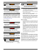
Installation Guidelines For 60 Hz EcoGen™ Generators YES or NO Æ ENTER - 14 + * Select Hour (0-23) Å Cold Smart Start? Fuel Selection + NG or LP - No + Yes or No - Setup Wi-Fi? ENTER + English + Espanol + Francais + Portuguese + ...... - Language Note: If language was previously programmed this goes directly to “Select Hour” Use UP and DOWN arrows. to select YES or NO. Press ENTER.
38 ENTER SUB MENUS DATE/TIME * * Re-try using a higher quality USB drive. File names on the USB cannot have more than 8 characters. Possible Message(s): Corrupted File Invalid File File Not Found Unsupported Device* Switched to OFF Hours of Protection 0 (H) ENTER SETUP WIFI SYSTEM - 0 + Select Minute (0-59) ENTER ESC * ENTER ENTER - 13 + USB: X.XX Current: V X.
Control Panel Startup/Testing Check Manual Transfer Switch Operation DANGER Electrocution. High voltage is present at transfer switch and terminals. Contact with live terminals will result in death or serious injury. (000129) If installed with a transfer switch, see Manual Transfer Operation section of owner’s manual for operating procedures. Electrical Checks DANGER Electrocution. High voltage is present at transfer switch and terminals. Contact with live terminals will result in death or serious injury.
Control Panel Startup/Testing Generator Tests Under Load DANGER Electrocution. Do not manually transfer under load. Disconnect transfer switch from all power sources prior to manual transfer. Failure to do so will result in death or serious injury, and equipment damage. (000132) Proceed as follows to test unit with electrical loads applied when unit is equipped with a transfer switch and with off-grid mode DISABLED: 1. Verify generator is OFF.
Control Panel Startup/Testing Checking Automatic Operation Proceed as follows to check system for correct automatic operation when unit is equipped with a transfer switch and with off-grid mode DISABLED: 1. Verify generator is OFF. 2. Install front cover of transfer switch. 3. Turn on utility power supply to transfer switch using the means provided (such as a utility MLCB). NOTE: Transfer switch will transfer to utility position. 4.
Control Panel Startup/Testing This page intentionally left blank.
Troubleshooting Section 8: Troubleshooting Generator Troubleshooting Problem Engine will not crank Cause Correction Blown fuse. Correct short circuit condition by replacing 7.5 A fuse in generator control panel. Contact an IASD if fuse continues to blow. Loose, corroded, or faulty battery cables. Faulty starter contact. Tighten, clean, or replace as necessary.* Faulty starter motor.
Troubleshooting Problem Cause Correction MLCB (generator disconnect) is OFF (OPEN). Reset generator disconnect to ON (CLOSED). Faulty transfer switch coil. No transfer to standby after utility source failure ** Unit consumes large amounts of oil Wi-Fi network connection broken or intermittent Faulty transfer relay. Transfer relay circuit open. Contact an IASD for assistance. Faulty control logic board. Engine may be warming up. See Cold Smart Start. Check controller screen to verify status.
Quick Reference Guide Section 9: Quick Reference Guide System Diagnosis To clear an active alarm, press OFF mode button on control panel, then ENTER button. Then press AUTO mode button. Contact an IASD if alarm reoccurs. Active Alarm NONE LED Problem FLASHING Unit running in AUTO but GREEN no power in house. Things to Check Check MLCB (generator disconnect). Solution Check MLCB. If it is ON, contact an IASD. HIGH TEMPERATURE RED Unit shuts down during operation.
Quick Reference Guide Active Alarm LED Problem OVERVOLTAGE RED Unit will not start in AUTO with utility loss. AUXILIARY SHUTDOWN RED Unit will not start. Things to Check Solution Check LED’s / Screen Contact an IASD. for alarms. Check auxiliary Set auxiliary shutdown switch(es) to shutdown switch(es). CLOSED (I). LOW BATTERY YELLOW Clear alarm. Using control panel, check battery by navigating to BATTERY MENU option from MAIN MENU.
Accessories Section 10: Accessories Performance enhancing accessories are available for air-cooled generators. Accessory Cold Weather Accessories*— • Battery Pad Warmer • Oil Warmer • Breather Warmer Description • Recommended in areas where temperatures fall below 0 °F (-18 °C). (Not necessary for use with AGM-style batteries) • Recommended in areas where temperatures fall below 0 °F (-18 °C). • Recommended in areas where heavy icing occurs.
Accessories This page intentionally left blank.
Diagrams Section 11: Diagrams Installation Drawing (10000037315 rev A—1 of 2) MOUNTING TO CONCRETE PAD HOLE LOCATIONS FOR OPTIONAL MOUNTING TO A CONCRETE PAD 521 [20.5] 16 [5/8] DIA. CLEARANCE HOLE (3) PLACES, 10 [3/8] DIA. MASONRY ANCHOR BOLTS RECOMMENDED 19.7 [7.7] 457 [18.0] 393 [15.5] 68 [2.
Diagrams Installation Drawing (10000037315 rev B—2 of 2) AIR INTAKE 457 [18.0] MINIMUM OPEN AREA 914 [36.0] MINIMUM OPEN AREA AIR INTAKE AIR OUTLET 914 [36.0] MINIMUM OPEN AREA TOP VIEW 914 [36.0] MINIMUM OPEN AREA "DO NOT LIFT BY ROOF" LIFTING HOLES 4 CORNERS: 30 [ 1.2] - MUST BE LIFTED WITH STEEL RODS - RECOMMENDED LIFTING ROD SIZE: 25 [ 1.0] RIGHT VIEW INTAKE PANEL REMOVED 1218 [48.0] RIGHT SIDE VIEW 1232 [48.5] 127 [5.
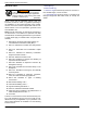
Installation Guidelines For 60 Hz EcoGen™ Generators DC DISTRIBUTION PANEL 12V/24V/48V AC DISTRIBUTION PANEL 120/240V *House Loads must be less than 10 kW or 2 hp HOUSE LOADS* HOUSE LOADS* 120V/240V CHARGER SUPPLY TWO-WIRE START BATTERY 12V/24V/48V INVERTER TWO-WIRE START ENGINE START BATTERY CHARGER 12 VOLT ENGINE START BATTERY ENGINE CONTROLLER BATTERY VOLTAGE SENSING TWO-WIRE START GENERATOR BATTERY CHARGER ALTERNATOR INVERTER/CHARGER 120/240V OUTPUT ECOGEN - TYPICAL OFF-GRID APPLICA
OIL DIPSTICK AND FILL VENT HOSE 52 ENGINE-OUT HOSE ENGINE-IN HOSE (TO OIL PUMP) OIL MAKE UP SYSTEM SCHEMATIC (NOT TO SCALE) 008706 Diagrams Oil Make Up System Schematic Installation Guidelines For 60 Hz EcoGen™ Generators
Diagrams This page intentionally left blank.
Diagrams This page intentionally left blank.
Part No. 10000032205 Rev. B 12/17/2018 ©2018 Generac Power Systems, Inc. All rights reserved Specifications are subject to change without notice. No reproduction allowed in any form without prior written consent from Generac Power Systems, Inc. Generac Power Systems, Inc. S45 W29290 Hwy. 59 Waukesha, WI 53189 1-888-GENERAC (1-888-436-3722) www.generac.