
Installation Guide

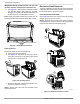


Table Of Contents
- Installation Guidelines 60 Hz Air-Cooled Generators
- Table of Contents
- Section 1: Safety Rules & General Information
- Section 2: Unpacking and Inspection
- Section 3: Site Selection and Preparation
- Section 4: Generator Placement
- Section 5: Fuel Conversion / Gas Connections
- Section 6: Electrical Connections
- Section 7: Control Panel Startup / Testing
- Section 8: Troubleshooting
- Section 9: Quick Reference Guide
- Section 10: Accessories
- Section 11: Diagrams

Site Selection and Preparation
14 Installation Guidelines for 60 Hz Air-Cooled Generators
Potential CO Entry Points
See Figure 3-1. Generator exhaust can enter a structure
through large openings, such as windows and doors.
However, exhaust and CO can also seep into the struc-
ture through smaller, less obvious openings.
Protect the Structure
Verify structure itself is correctly caulked and sealed to
prevent air from leaking in or out. Voids, cracks, or open-
ings around windows, doors, soffits, pipes, and vents can
allow exhaust gas to be drawn into the structure.
Some examples of potential entry points are described
and included in, but not limited to, the accompanying
table.
Figure 3-1. Carbon Monoxide—Potential Entry Points
ID Entry Point Description / Comments
A Windows and doors Architectural details which can be (or are) opened to admit fresh air into the structure.
B Garage door CO can leak into garage if door is open, or does not seal correctly when closed.
C Attic vent Attic vents, ridge vents, crawl space vents, and soffit vents can all admit generator exhaust.
D Basement windows Windows or hatches allowing ventilation to or from lower level of a structure.
E
Furnace intake /
exhaust vent
Air intake and exhaust pipes for furnace.
F Wall cracks
Includes (but not limited to) cracks in wall, foundation, mortar, or air gaps around doors,
windows, and pipes. See Protect the Structure.
G Dryer vent Exhaust duct for clothes dryer.
H Airflow restrictions
Structural corners and locations with heavy vegetation restrict airflow. Exhaust gases can collect
in such areas.
J Make up air system
IMPORTANT NOTE: Mechanical and gravity outdoor air intake openings for HVAC supply
air systems shall be located not less than 10 feet (3048mm) horizontally from the
generator enclosure. See Section 401 in the ICC Mechanical Code for any additional
requirements.
A
K
B
A
C
G
A
A
A
F
D
E
A
H
A
C
008781
J