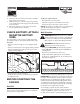
Owner’s Manual Parts Included* Table of Contents • Generator • Wheel kit • Storage Cover • Battery • Battery Float Charger • Battery Charge Cables • Spare Air Filter and Pre-cleaner • Spare Oil Filter • (2) Spare Spark Plugs • Spark Plug Wrench • (2) Locking 30 Amp Plugs • Locking 20 Amp Plug • (2) Engine Oil • Owner's Manual • Engine Manual *If any parts are missing or damaged, call 1-800-270-1408. Safety Rules . . . . . . . . . . . . . . . . . . . . . . . . . . . . . . . . . . . . 2-3 Assembly . . . .
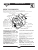
10000EXL Extended Life Generator EQUIPMENT DESCRIPTION DANGER Running generator gives off carbon monoxide, an ordorless, colorless, poison gas. Breathing carbon monoxide will cause nausea, fainting or death. Read this manual carefully and become familiar with your generator. Know its applications, its limitations and any hazards involved. This generator is an engine–driven, revolving field, alternating current (AC) generator.
10000EXL Extended Life Generator WARNING WARNING Running engines produce heat.Temperature of muffler and nearby areas can reach or exceed 150°F (65°C). Severe burns can occur on contact. Gasoline and its vapors are extremely flammable and explosive. Fire or explosion can cause severe burns or death. • DO NOT touch hot surfaces. • Allow equipment to cool before touching. WHEN ADDING FUEL • Turn generator OFF and let it cool at least 2 minutes before removing gas cap.
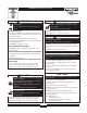
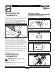
10000EXL Extended Life Generator INSTALL WHEEL KIT Your generator requires some assembly and is ready for use after it has been properly serviced with the recommended oil and fuel. The wheel kit is designed to greatly improve the portability of your generator. NOTE: Wheel kit is not intended for over-the-road use. You will need a socket wrench with 1/2" or 13mm sockets and a needle-nose plier to install this kit.
10000EXL Extended Life Generator 8. Attach the vibration mounts to the support leg with a 30mm capscrew and lock nut. 9. With the wheels on, secure the support leg assembly to the cradle with 20 mm long capscrews, flat washers, and lock washers. 10. Check each fastener to ensure it is secure and the tires are inflated between 15-40 PSI. To fill your engine with oil: • Place generator on a level surface. • Follow the oil grade recommendations and oil fill instructions given in the engine owner’s manual.
10000EXL Extended Life Generator KNOW YOUR GENERATOR Read this owner’s manual and safety rules before operating your generator. Compare the illustrations with your generator, to familiarize yourself with the locations of various controls and adjustments. Save this manual for future reference.
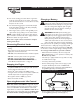
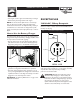
10000EXL Extended Life Generator GROUNDING THE GENERATOR Starting the Engine The National Electrical Code requires that the frame and external electrically conductive parts of this generator be properly connected to an approved earth ground. Local electrical codes may also require additional grounding of the unit. For that purpose, a GROUNDING WING NUT is provided on the generator end (Figure 4). 1. Disconnect all electrical loads from the generator.
10000EXL Extended Life Generator Charging a Battery 5A. For electric starting, press start switch on generator cradle.To prolong the life of the starter components, press the starter button for no more than 15 seconds, and pause for 30 seconds. WARNING! Storage batteries give off explosive hydrogen gas while recharging. An explosive mixture will remain around the battery for a long time after it has been charged.
10000EXL Extended Life Generator RECEPTACLES • Start engine. Let the engine run while battery recharges. • When battery has charged, shut down engine NOTE: Use an automotive hydrometer to test battery state of charge and condition. Follow the hydrometer manufacturer’s instructions carefully. Generally, a battery is considered to be at 100% state of charge when specific gravity of its fluid (as measured by hydrometer) is 1.260 or higher.
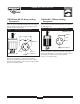
000EXL Extended Life Generator 120/240 Volt AC, 30 Amp, Locking Receptacle 120 Volt AC, 30 Amp Locking Receptacle Use a NEMA L14–30 plug with this receptacle. Connect a 4–wire cord set rated for 250 Volt AC loads at 30 Amps (or greater) (Figure 12).You can use the same 4–wire cord if you plan to run a 120 Volt load. Use a NEMA L5–30 plug with this receptacle. Connect a 3–wire cord set rated for 125 Volt AC loads at 30 Amps to the plug (Figure 13).
10000EXL Extended Life Generator 120 Volt, 20 Amp Locking Type Receptacle Figure 15 — 120 Volt AC, 20 Amp, Duplex Receptacle Use a NEMA L5–20 plug with this receptacle. Connect a 3–wire cord set rated for 125 Volt AC loads at 20 Amps to the plug (Figure 14). Figure 14 — 120 Volt AC, 20 Amp, Locking Receptacle 3-Wire Cord Set NEMA L5-20 Neutral 120V Hot Use each receptacle to operate 120 Volt AC, single–phase, 60 Hz electrical loads requiring up to 2,400 watts (2.4 kW) at 20 Amps of current.
10000EXL Extended Life Generator DON'T OVERLOAD YOUR GENERATOR 4. Plug in and turn on the next load. 5. Again, permit the generator to stabilize. 6. Repeat steps 4 and 5 for each additional load. NEVER add more loads than the generator capacity.Take special care to consider surge loads in generator capacity, as described above. Capacity You must make sure your generator can supply enough rated (running) and surge (starting) watts for the items you will power at the same time.
10000EXL Extended Life Generator SPECIFICATIONS Generator Maintenance Maximum Surge Watts . . . . . . . . . . . . . . . .12,500 watts Continuous Wattage Capacity . . . . . . . . . .10,000 watts Power Factor . . . . . . . . . . . . . . . . . . . . . . . . . . . . . .1.0 Rated Maximum Continuous AC Load Current: At 120 Volts . . . . . . . . . . . . . . . . . . . . . . .83.3 Amps At 240 Volts . . . . . . . . . . . . . . . . . . . . . . .41.7 Amps Phase . . . . . . . . . . . . . . . . . . . . . . . . . . . .
10000EXL Extended Life Generator STORAGE Engine Storage See engine owner’s manual for instructions. The generator should be started at least once every seven days and allowed to run at least 30 minutes. If this cannot be done and you must store the unit for more than 30 days, use the following guidelines to prepare it for storage. Other Storage Tips • To prevent gum from forming in fuel system or on essential carburetor parts, add fuel stabilizer into fuel tank and fill with fresh gasoline.
10000EXL Extended Life Generator TROUBLESHOOTING Problem Engine is running, but no AC output is available. Engine runs good at noload but “bogs” down" when loads are connected. Cause Correction 1. 2. 3. 4. One of the circuit breakers is open. Fault in generator. Poor connection or defective cord set. Connected device is bad. 1. 2. 3. 4. 1. 2. 3. Short circuit in a connected load. Engine speed is too slow. Generator is overloaded. 1. 2. 3. 4. 1. 2. 3. 4. 5. 6.
10000EXL Extended Life Generator SCHEMATIC 16
10000EXL Extended Life Generator WIRING DIAGRAM 17
10000EXL Extended Life Generator EXPLODED VIEW – MAIN UNIT 18
10000EXL Extended Life Generator PARTS LIST – MAIN UNIT Item 1 2 3 4 5 6 7 8 9 10 11 12 13 14 15 16 17 18 19 20 21 22 23 24 25 26 27 28 29 31 32 33 34 35 36 37 38 39 40 41 42 43 44 45 46 47 48 49 50 51 52 54 55 56 Part # NSP JB4509AGS A77304GS JB5567GS 80270GS 78299GS B4325GS 38353GS 78831BGS B1997GS A189487GS 83465GS 87680GS 23152GS 22237GS 22241GS 77816GS 22131GS J93074GS 186076GS 19553621GS 45757GS 75246GS 22145GS 26850GS 20566GS B4986GS 92982GS 189409GS 52857GS 187049GS 93826GS 76040GS B2153GS 73054GS
10000EXL Extended Life Generator EXPLODED VIEW – CONTROL PANEL 20
10000EXL Extended Life Generator PARTS LIST – CONTROL PANEL Item 1 2 3 4 5 6 7 8 9 10 11 12 13 14 16 17 18 19 20 21 22 23 24 25 26 27 28 29 30 31 32 33 34 35 36 37 38 39 40 41 42 43 44 Part # AB4432GS B95906GS 43437GS 68759GS 68868GS B5112GS 186102GS 90576GS B4262GS 87962GS 93929GS 51715GS 22264GS 43181GS 38150GS 23365GS 90418GS 43182GS 75207AGS 78653GS 93986GS 91526GS 49226GS 23897GS 75207GS 74190GS 92953GS 80077GS 94117GS 84028GS 65795GS 84135GS 79224GS 186200GS B4893GS 82538GS 51714GS 51716GS B4445GS B
10000EXL Extended Life Generator EXPLODED VIEW AND PARTS LIST – WHEEL KIT Item 1 2 3 4 5 6 7 8 9 10 11 12 13 14 15 16 17 18 Part # BB5586GS B4605GS 39287GS 22145GS 49820GS 187104GS B4135GS B93394GS 191413GS 52858GS 22129GS 39253GS 42909GS 191267BGS B89635GS 89742GS 22247GS 191265GS Qty Description 2 HANDLE (Includes Item 2) 2 GRIP 2 SCREW 6 WASHER 2 NUT, Nylok 4 WASHER, Nylon 2 PIN, with Lanyard 1 LEG, Mounting Support 1 VIBE MOUNT, with Washer 1 NUT, Lock 2 WASHER, Lock 2 SCREW 1 SCREW 1 AXLE 2 SPACER,
10000EXL Extended Life Generator EXPLODED VIEW AND PARTS LIST – ALTERNATOR Item 1 2 3 4 5 6 7 8 9 11 12 14 15 16 17 18 19 Part # B4906GS B4907GS B4908GS B4909GS B4910GS B4911GS B4912GS B4913GS B4914GS B4916GS 191297GS B4919GS B4920GS 49820GS 188928GS 22473GS 49813GS Qty Description 1 SHIELD, Front 2 GRID, Front 1 BOLT, Shaft Stay 4 BOLT, Stay 1 ASSY, Housing 1 CAP 1 COVER, Blind End 1 COVER,Top Black 2 CAPACITOR 1 CAPACITOR, Diode + Varistor + EMC 1 ASSY, Rotor (Includes Item 11) 2 SCREW 8 SCREW 1 NUT,
LIMITED WARRANTY GENERAC PORTABLE PRODUCTS OWNER WARRANTY POLICY Effective October 1, 2001 LIMITED WARRANTY "Generac Portable Products, LLC will repair or replace, free of charge, any part, or parts of the equipment that are defective in material or workmanship or both.Transportation charges on parts submitted for repair or replacement under this Warranty must be borne by purchaser. This warranty is effective for the time periods and subject to the conditions provided for in this policy.