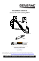
Installation Manual Generac PV Link™ and SnapRS™ 010023 006087 WARNING Loss of life. This product is not intended to be used in a critical life support application. Failure to adhere to this warning could result in death or serious injury. (000209b) Register your Generac product at: https://pwrfleet.generac.com 1-888-GENERAC (888-436-3722) Para español, visita: http://www.generac.com/service-support/product-support-lookup Pour le français, visiter: http://www.generac.
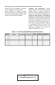
Use this page to record important information about your Generac Product Record PV Link™ and SnapRS™ information for your PWRcell system on this page. When contacting a Generac Products Authorized Service Dealer (ASD) about parts and service, always supply complete model number and serial number information. Operation and Maintenance: Proper maintenance and care of the energy storage system ensures a minimum number of problems and keeps operating expenses at a minimum.
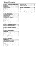
Table of Contents Section 1 Introduction and Safety 1 Introduction ..................................... 1 Safety Rules .................................... 1 General Hazards ............................. 2 PVRSE Warning .............................. 2 Electrical Hazards ........................... 3 Section 2 General Information ..... 5 PV Link Specifications ..................... 5 SnapRS Specifications .................... 5 Unit Dimensions .............................. 6 About PV Link ................
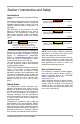
Section 1 Introduction and Safety Introduction Thank you for purchasing a Generac PWRcell product. This manual provides instructions for installing PV Link and SnapsRS devices. Consult the installation and operation manuals for other Generac PWRcell system components, as applicable. The information in this manual is accurate based on products produced at the time of publication. The manufacturer reserves the right to make technical updates, corrections, and product revisions at any time without notice.
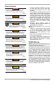
General Hazards DANGER Automatic start-up. Disconnect utility power and render unit inoperable before working on unit. Failure to do so will result in death or serious injury. (000191) WARNING Risk of injury. Do not operate or service this machine if not fully alert. Fatigue can impair the ability to service this equipment and could result in death or serious injury. (000215) WARNING Loss of life. This product is not intended to be used in a critical life support application.
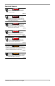
Electrical Hazards DANGER Electrocution. Water contact with a power source, if not avoided, will result in death or serious injury. (000104) DANGER Electrocution. In the event of electrical accident, immediately shut power OFF. Use non-conductive implements to free victim from live conductor. Apply first aid and get medical help. Failure to do so will result in death or serious injury. (000145) DANGER Electrocution. Turn battery disconnect OFF and de-energize REbus before touching terminals.
This page is intentionally left blank 4 Installation Manual for PV Link and SnapRS
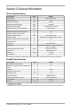
Section 2 General Information PV Link Specifications Description Units S2502 Rated power W 2500 (continuous) Peak efficiency % 99 MPPT input voltage VDC 60–360 Rated power input voltage VDC 200–360 Maximum input voltage VDC 420 (absolute maximum) A ºF (ºC) 13 @ 122 (50) Maximum input current (short circuit) A 18 Maximum output current (fault) A 10 VDC 420 (open circuit) Nominal output - REbus DC nanogrid (380 VDC + data) Maximum output current (continuous) A 8 Standby power
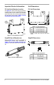
Important Product Information Unit Dimensions PV Link Serial Number Location PV Link Dimensions See Figure 2-1. Serial number tag (A) includes a removable layer that can be peeled off leaving the underlying label in place. Adhere the removable layer to the inside cover of this manual and record the information from this tag in Table 1: PV Link and SnapRS Important Information. A r A B C Figure 2-3.
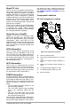
About PV Link The PV Link is a nonisolated, interleaved DCDC converter that boosts PV input to a higher voltage and outputs it to Rebus™, Generac’s regulated 380 VDC bus. The PV Link provides droop-mode power management, enabling multiple optimizers to connect in parallel on a common bus, and its DC output carries a bidirectional power line communication (PLC) protocol for communicating with inverters and other devices on REbus.
SnapRS Component Locations B 010050 A Figure 2-6.
Section 3 Installation Design Installation Design Worksheet Use this worksheet to determine the maximum number of PV modules of a given type that can be connected to a PV Link. 3. Divide the PV Link VMP (Voltage at Maximum Power) by the panel VMP and round down to determine the number of panels that can be connected in series to the PV Link without exceeding maximum power voltage. NOTE: Fewer PV modules can be used as long as the minimum MPPT input voltage is met. PV Link Max VMP 1.
This page is intentionally left blank 10 Installation Manual for PV Link and SnapRS
Section 4 PVRSS Compliance Guidelines 2011 NEC and Older Editions 2011 NEC and older editions do not require PVRSS compliance. NOTE: The PV Link will still provide 2014 NEC compliant PV Rapid Shutdown. 2014 NEC The 2014 NEC 690.12 introduced a new requirement for PV systems that is commonly referred to as PV rapid shutdown. To meet 2014 NEC compliance: 1. Install the PWRcell inverter as specified in the Generac PWRcell Inverter Installation Manual. 2. Install the PV Link as specified in this manual. 3.
This page is intentionally left blank 12 Installation Manual for PV Link and SnapRS
Section 5 Mounting and Connecting Installation Guidelines Installing to Nonmetallic or Ungrounded Structures CAUTION Equipment damage. Never leave the PV Link MC4 connectors open and exposed to the atmosphere overnight or during rain. Doing so could cause equipment failure. (000657) C A PV Link / S2502 SnapRS™ compatible substring optimizer PV rapid shutdown system equiptment IMPORTANT INSTALLATION INSTRUCTIONS: ≤ 420Voc ≤ 420Voc Input: Max 420V temperature corrected Voc. SINGLE STRING INPUT.
Connecting to Inverter Connecting PV Modules CAUTION CAUTION Equipment damage. Connect the PV Link output to a REbuscompatible device (± 190 VDC nominal regulated DC bus) only. Connecting to conventional PV inverters or any other device could cause equipment damage. Equipment damage. Never leave the PV Link MC4 connectors open and exposed to the atmosphere overnight or during rain. Doing so could cause equipment failure. (000659) See Figure 5-3.
2017 and 2020 NEC Compliant Systems To install SnapRS devices: 1. See Figure 5-4. For each PV module in the PV string, connect the positive (+) end of one SnapRS device (C) to the negative (-) whip of the PV Module (D). 2. Connect the negative (-) end of each SnapRS device to the positive (+) whip of the next PV module in the series. 3. Connect the PV string positive lead to PV Link (B) at the location marked PV Substring Input + (F). See Component Locations for more information. 4.
NOTE: See Figure 5-5. When dual strings are connected in parallel, each string must use the same number of the same type of PV modules, and there must be one SnapRS device for each module in the array. A B E E D C Figure 5-5.
Section 6 Operating Instructions User Interface via Inverter PV Link Information and control features are available on the PWRcell inverter control panel when REbus is energized. See the Generac PWRcell Inverter Owner’s Manual for more information. See Figure 6-1. To access the device page for each PV Link, use left or right arrow buttons (A) on the inverter control panel to scroll through the pages.
6. See Figure 6-5. The LCD will display Testing PRVSS during the testing process. Upon completion, the LCD will read Low Sun or Making Power, depending upon available PV voltage. PWRcell X7602 -xx Photovoltaics testing PVRSS Power: 0W PV Voltage: 115v E-total: 59.0kWh 7. Complete steps 1-6 for each PV link in the system. NOTE: To verify a PV Link is working properly, navigate to the Mod.Settings page and confirm the SnapRSInstalld value matches the number of SnapRS devices connected to that PV Link.
Disabling PV Link NOTE: Disabling a PV Link does NOT deenergize the PV array if SnapRS devices are not installed. If SnapRS devices are installed, in-array voltages are limited to less than 80 VDC. NOTE: Disabling PV Link does not de-energize the DC bus if other devices are providing power to the DC bus. NOTE: The disabled/enabled state of each PV Link persists through AC power outages and DC bus power cycling. To disable a PV Link: 1.
This page is intentionally left blank 20 Installation Manual for PV Link and SnapRS
Section 7 Maintenance Service WARNING Equipment damage. Never open the PV Link. The optimizer is factory-sealed and contains no fieldserviceable parts. Opening the optimizer could result in equipment damage. (000655) Maintenance See Figure 7-1. To ensure maximum performance, keep heatsink fins (A) free of leaves and other debris.
This page is intentionally left blank 22 Installation Manual for PV Link and SnapRS
Section 8 Troubleshooting CAUTION Equipment damage. Connect the PV Link output to a REbuscompatible device (± 190 VDC nominal regulated DC bus) only. Connecting to conventional PV inverters or any other device could cause equipment damage. (000659) There are no functional tests that can be performed on SnapRS devices in the field. However, some simple digital multimeter (DMM) checks can confirm the general health of a SnapRS device.
This page is intentionally left blank 24 Installation Manual for PV Link and SnapRS
Part No. DMAN00013 Rev. B 05/07/2020 ©2020 Generac Power Systems, Inc. All rights reserved Specifications are subject to change without notice. No reproduction allowed in any form without prior written consent from Generac Power Systems, Inc. Generac Power Systems, Inc. S45 W29290 Hwy. 59 Waukesha, WI 53189 1-888-GENERAC (1-888-436-3722) www.generac.