Installation Manual Generac PWRcell™ Inverter 009954 WARNING Loss of life. This product is not intended to be used in a critical life support application. Failure to adhere to this warning could result in death or serious injury. (000209b) Register your Generac product at: https://register.generac.com/ 1-888-GENERAC Register (888-436-3722) your Generac product at: WWW.GENERAC.COM Para español, visita: http://www.generac.
Use this page to record important information about your Generac Product Record the information found on your unit data label on this page. See Serial Number Locations. When contacting an Independent Authorized Service Dealer (IASD) or Generac Customer Service, always supply the complete model number and serial number of the unit. Table 1: Generac PWRcell Inverter Important Information Unit Model Number Unit Serial Number Date Purchased Commissioning Date WARNING CANCER AND REPRODUCTIVE HARM www.
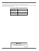
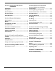
Section 1: Safety Rules & General Information Section 5: Electrical Connections Introduction ..........................................................1 Generac PWRcell Inverter Wiring Compartment ..................................................... 13 Safety Rules .........................................................1 Accessing Wiring Compartment ...................... 13 General Hazards ..................................................2 Knockout Dimensions and Locations .............
This page intentionally left blank.
Safety Rules & General Information Section 1: Safety Rules & General Information Introduction Safety Rules Thank you for purchasing a Generac PWRcell™ Inverter. The Generac PWRcell Inverter is a storage-ready inverter that connects to the Generac PV Link™ and Generac PWRcell Batteries to form the Generac PWRcell system. This manual provides instructions for installing the Generac PWRcell Inverter, including mounting, wiring, and battery integration information.
Safety Rules & General Information General Hazards WARNING DANGER Electrocution. Do not wear jewelry while working on this equipment. Doing so will result in death or serious injury. (000188) DANGER Equipment damage. Connecting inverter to electric utility grid must only be done after receiving prior approval from utility company. Failure to do so could result in equipment or property damage. (000640) • Connecting Generac PWRcell Inverter to the elec- Automatic start-up.
Safety Rules & General Information Electrical Hazards Safety Shutdown DANGER DANGER Electrocution. Water contact with a power source, if not avoided, will result in death or serious injury. (000104) DANGER Electrocution. PWRcell Battery front cover should be removed by a qualified technician only. Removing the front cover could result in death, serious injury, equipment or property damage. (000604) DANGER Electrocution. In the event of electrical accident, immediately shut power OFF.
Safety Rules & General Information This page intentionally left blank.
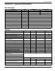
General Information Section 2: General Information Specifications Description Units X7600 Series X11400 Series Max. cont. AC power @ 50ºC kW 7.6 11.4 Grid Voltage VAC 240 (1-ph) 120/208 (3-ph) Max cont. REbus current (peak) A 20 30 Max cont.
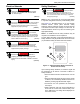
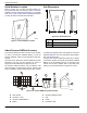
General Information Serial Number Location Unit Dimensions Refer to Figure 2-1 to locate unit serial number (A). Record the information from this tag in Table 1: Generac PWRcell Inverter Important Information on the inside front cover of this manual. When requesting assistance you may be asked to provide this information. 1 A B A C 009955 Figure 2-2. Unit Dimensions 009954 Figure 2-1. Serial Number Location A 24.5 in (622 mm) B 19.
General Information Component Locations See Figure 2-5. Generac PWRcell is controlled through the Generac PWRcell Inverter control panel. The inverter control panel is used for adjusting system settings and for interacting with devices. A C LED Indicators See Figure 2-5 for LED locations. REbus Status LED REbus Status LED (C) communicates REbus nanogrid status through LED color. • Green – all devices are functioning normally and are either generating power or ready to generate power.
General Information This page intentionally left blank.
Location and Compliance Section 3: Location and Compliance Location Note on DC Wiring and the NEC When installing the Generac PWRcell Inverter, consider the following: • The unit can be installed in indoor or outdoor locations. • The unit must be readily accessible. • The inverter installation location must meet the working space requirements in NEC Article 110.26. Some electricians or installers may be unfamiliar with DC wiring in a residential setting. Note the following: • NEC 690.
Location and Compliance Voltage and Frequency Trip Thresholds This unit or system is provided with fixed trip limits and shall not be aggregated above 30 kW on a single point of common connection. All Generac PWRcell Inverters are shipped from the factory in compliance with all UL1741 requirements, including IEEE1547.
Installing PWRcell Inverter Section 4: Installing PWRcell Inverter Mounting the Inverter 2. Verify fasteners are suitable for the mounting surface and can adequately secure the inverter to the wall. See Specifications for unit weight. WARNING Equipment damage. Mount inverter to a strong, stable surface. Never mount to drywall, plaster, or other non-structural wall treatments. Failure to mount inverter to a strong, stable surface could result in equipment or property damage. (000641) 1.
Installing PWRcell Inverter This page intentionally left blank.
Electrical Connections Section 5: Electrical Connections Generac PWRcell Inverter Wiring Compartment C I F E G D H J L A B K Figure 5-1.
Electrical Connections Knockout Dimensions and Locations NOTE: All knockouts are combination knockouts. Table 5-3. Combination Knockout Size and Quantity See Figure 5-3 for knockout locations and Table 5-3 for available knockout sizes and quantities. When using knockouts: • Install reducing washers to accommodate smaller Combination Knockout Size Quantity 3/4” X 1” 6 1/2” X 3/4” 7 conduit sizes. • Install rain-tight or wet compliance with UL514B. locations hubs in 1.969 50 2.638 67 1.
Electrical Connections Wiring Guidelines Grounding Bar Wiring DANGER WARNING Electrocution. Verify all system voltages are safe before wiring. Disconnect all AC and DC sources of power before touching terminals. Failure to ensure no dangerous voltages are present on conductors and terminals before wiring will result in death or serious injury. (000642) Equipment damage. Never connect REbus conductors to ground. Connecting REbus conductors to ground could result in equipment or property damage.
Electrical Connections DC Wiring AC Wiring WARNING Equipment damage. Connect only to REbus-compatible devices to the DC bus. Never connect to any other DC power source. Connecting to other DC power sources could result in equipment damage. (000598) WARNING Equipment damage. Do not connect PV string output directly to inverter. PV must be connected via Generac PWRcell PV Link. Connecting PV output directly to inverter could result in equipment or property damage.
Electrical Connections Protected Load WARNING Equipment damage. Never connect protected loads terminals to other sources of power, including any other inverter, the utility grid, or a generator. Doing so could result in equipment or property damage. (000648) WARNING Equipment damage. Never connect protected loads output from multiple inverters in parallel. Doing so could result in equipment or property damage.
Electrical Connections Connecting Ethernet IMPORTANT NOTE: Generac requires all PWRcell system components to be connected to the Internet and to maintain such connection throughout the warranty period. Internet connectivity is established via the PWRcell Inverter. By installing the PWRcell Inverter and connecting it to the Internet, Customer agrees that Generac may remotely monitor the use and condition of the system and update the system's software and firmware, as necessary, without further notice.
Electrical Connections Connecting CTs to the Inverter • See Figure 5-8. Connect CTs to the inverter using a RJ-45 connector and Category 5 (Cat 5) Ethernet cable. • CT input jack (H) is a double-stacked RJ-45 jack. NOTE: RJ-45 Breakout Adapter is included in the Generac PWRcell Kit. NOTE: If the RJ-45 Breakout Adapter is not available, the CT leads can be wired to a Cat 5 cable. Either the top or bottom jack may be used. Table 5-8.
Electrical Connections Table 5-10.
Commissioning and Setup Section 6: Commissioning and Setup System Configuration Inverter Power-up The Generac PWRcell system is a flexible, highly customizable system that can be configured in a number of ways to meet customer need. Correct system configuration requires selecting the right equipment and the correct operational mode for the system. See the Generac PWRcell Inverter Owner’s Manual for information on operational modes and other userconfigurable settings.
Commissioning and Setup 2. See Figure 6-3. A list of operational modes will be displayed with the current mode marked with an asterisk. NOTE: The list of modes may not include all those shown in Figure 6-3. Configuring Custom Grid Settings (optional) By default, all Generac PWRcell Inverters ship in compliance with UL1741, including IEEE1547. If the system needs to be configured to comply with a different grid interconnection standard, activate the new configuration before proceeding.
Commissioning and Setup 5. See Figure 6-8. Arrow right and press center button to Confirm. Configuring and Running a TOU Schedule 1. See Figure 6-10. Navigate to the Generac Beacon device page and press the center button to enter the device menu. 010017 Figure 6-8. Enabling Inverter (3 of 4) 010109 6. See Figure 6-9. The inverter is enabled. It will create voltage at the DC terminals and begin communicating over REbus.
Commissioning and Setup 5. Use the up and down arrows to highlight TOU Schedule and press the center button to select. 6. Use the up and down arrows to adjust the TOU Schedule. Once the desired value is set, press the center button to exit edit mode. NOTE: See the latest Time of Use Program Guide for current TOU schedule values. The program guide is available at www.generac.com. 7. Set the Time Zone to the desired location based on Table 1: Time Zone Codes.
Commissioning and Setup Disabling Generac Beacon Enabling Generac Beacon The scheduler can be disabled at any time. To disable the scheduler: 1. See Figure 6-18. Navigate to the Generac Beacon device page and press the center button to enter the device menu. Once the TOU Schedule is set, the scheduler will automatically enable itself and begin running. However, if the scheduler has been disabled for any reason, the scheduler must be enabled to run. To enable the scheduler: 1. See Figure 6-18.
Commissioning and Setup When the scheduler has been overridden: • Temporary Override will display on the home page, alternating with the words Scheduler Active and the name of the current operational mode. • See Figure 6-23. Running, Overridden will display on the Generac Beacon device page. Commissioning Generac Beacon NOTE: Follow all commissioning procedures for the Generac PWRcell Inverter and all connected REbus devices before commissioning the Generac Beacon.
Commissioning and Setup 4. See Figure 6-25. Use the up and down arrows to highlight Enable Ethernet then press the center button. Manually Configuring IP Settings NOTE: On networks not configured for DHCP, use the MAC address to locate the device on the network. To manually configure settings: 1. See Figure 6-28. Press the center button from the Ethernet settings screen and select IP Settings. 010046 Figure 6-25. Ethernet Configuration (2 of 4) NOTE: Select IP Settings for advanced settings. 5.
Commissioning and Setup Ethernet Troubleshooting Serial Number and Registration NOTE: Use a laptop or other device to verify your Internet connection is working properly before troubleshooting. NOTE: If it is not possible to connect the system to the Internet, please call Generac Customer Service at 1-888GENERAC (1-888-436-3722) to complete registration. For a successful connection the following must be valid: • The Internet LED on the control panel must be lit.
Maintenance Section 7: Maintenance Service Replacing Fuses DANGER WARNING Electrocution. Verify all system voltages are safe before wiring. Disconnect all AC and DC sources of power before touching terminals. Failure to ensure no dangerous voltages are present on conductors and terminals before wiring will result in death or serious injury. (000642) DANGER Equipment damage. Never replace a fuse with a different size or style.
Maintenance Recovery From an Error State To replace a fuse: 1. Initiate a Safety Shutdown and allow DC voltage to drop to a safe level. 2. Power down the inverter. 3. Disconnect all sources of AC and DC power. 4. Removing wiring compartment cover. See Accessing Wiring Compartment. 5. See Figure 7-2. Locate DC fuse holders (B) 6. Press fuse holder up and turn counterclockwise to release. 7. Remove fuse from fuse holder. 8. Insert replacement fuse into fuse holder. 9. Reinstall fuse holder.
Troubleshooting Section 8: Troubleshooting General Troubleshooting Some of the more common problems are listed in the table below. This information is intended to be a check or verification that simple causes can be located and fixed. It does not cover all types of problems. Procedures that require in-depth knowledge or skills should be referred to an Independent Authorized Service Dealer. Table 8-1.
Troubleshooting This page intentionally left blank.
Troubleshooting This page intentionally left blank.
Troubleshooting This page intentionally left blank.
® Part No. DMAN00007 Rev. A 10/25/19 ©2019 Generac Power Systems, Inc. All rights reserved. Specifications are subject to change without notice. No reproduction allowed in any form without prior written consent from Generac Power Systems, Inc. Generac Power Systems, Inc. S45 W29290 Hwy. 59 Waukesha, WI 53189 1-888-GENERAC (1-888-436-3722) www.generac.