Installation Guidelines Australian 50 Hz Air-Cooled Generators 8 kVA to 13 kVA WARNING Loss of life. This product is not intended to be used in a critical life support application. Failure to adhere to this warning could result in death or serious injury. (000209b) Register your Generac product at: WWW.GENERAC.COM 1-888-GENERAC (888-436-3722) Para español, visita: http://www.generac.com/service-support/product-support-lookup Pour le français, visiter : http://www.generac.
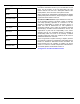
Use this page to record important information about your generator set. Model: Serial: Prod Date Week: Volts: LPV Amps: NG Amps: Hz: Phase: Controller P/N: Record the information found on your unit data label on this page. For the location of the unit data label, see your owner’s manual. The unit has a label plate affixed to the inside partition, to the left of the control panel console.
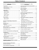
Table of Contents Section 1: Safety Rules & General Information Section 5: Fuel Conversion / Gas Connections Introduction ..........................................................1 Fuel Requirements and Recommendations ... 17 Read This Manual Thoroughly ....................................1 Fuel Conversion ................................................ 17 Safety Messages ..................................................1 Fuel Consumption .............................................
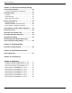
Table of Contents Section 7: Control Panel Start-Up/Testing Control Panel Interface .....................................35 Using the AUTO/MANUAL/OFF Buttons ................. 35 Generator Setup .................................................35 Activation .................................................................. 35 Cold Smart Start ....................................................... 38 Setting The Exercise Timer ....................................... 38 Before Initial Start-up ...........
Safety Rules & General Information Section 1: Safety Rules & General Information Introduction Thank you for purchasing this compact, high performance, air-cooled, engine-driven generator. It is designed to automatically supply electrical power to operate critical loads during a utility power failure. This unit is factory installed in an all-weather, metal enclosure that is intended exclusively for outdoor installation.
Safety Rules & General Information Safety Rules Study these SAFETY RULES carefully before installing, operating, or servicing this equipment. Become familiar with this installation manual, the owner’s manual, and with the unit. The generator can operate safely, efficiently, and reliably only if it is properly installed, operated, and maintained. Many accidents are caused by failing to follow simple and fundamental rules or precautions.
Safety Rules & General Information WARNING Environmental Hazard. Always recycle batteries at an official recycling center in accordance with all local laws and regulations. Failure to do so could result in environmental damage, death or serious injury. (000228) WARNING Injury and equipment damage. Do not use generator as a step. Doing so could result in falling, damaged parts, unsafe equipment operation, and could result in death or serious injury. (000216) Electrical Hazards DANGER Electrocution.
Safety Rules & General Information Fire Hazards Explosion Hazards DANGER WARNING Fire hazard. Do not obstruct cooling and ventilating airflow around the generator. Inadequate ventilation could result in fire hazard, possible equipment damage, death or serious injury. (000217) Explosion and fire. Fuel and vapors are extremely flammable and explosive. No leakage of fuel is permitted. Keep fire and spark away. Failure to do so will result in death or serious injury.
Safety Rules & General Information General Rules Battery Hazards DANGER DANGER Electrocution. Do not wear jewelry while working on this equipment. Doing so will result in death or serious injury. (000188) WARNING Loss of life. Property damage. Installation must always comply with applicable codes, standards, laws and regulations. Failure to do so will result in death or serious injury. (000190) DANGER Explosion. Do not dispose of batteries in a fire. Batteries are explosive.
Safety Rules & General Information Before You Begin • Contact the local inspector or city hall to be aware of all federal, state, and local codes that could impact the installation. Secure all required permits before starting the install. • Carefully read and follow all of the procedures and safety precautions detailed in the installation guide. If any portion of the installation manual, technical manual, or other factory-supplied documents is not completely understood, contact an IASD for assistance.
Unpacking and Inspection Section 2: Unpacking and Inspection General NOTE: Carefully inspect the contents for damage after unpacking. It is advised to unpack and inspect the unit immediately upon delivery to detect any damage that may have occurred in transit. Any claims for shipping damage need to be filed as soon as possible with the freight carrier. This is especially important if the generator will not be installed for a period of time. Unpacking 1. Remove outer shipping carton. 2. See Figure 2-1.
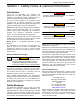
Unpacking and Inspection 7. See Figure 2-4. Two locks secure the lid; one on each side (A). Press down on the lid above the side lock, and unlock the latch to properly open the lid. 6. See Figure 2-3. Remove bolts and pallet brackets (A). Exercise caution when removing the generator. Dragging it off the pallet will damage the base. The generator must be lifted from the wooden pallet to remove. Bolts and pallet brackets are provided only for shipping purposes and can be discarded after removal. 8.
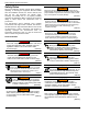
Unpacking and Inspection Intake Side Panel Removal 3. Lift the intake panel up and away from the generator. See Figure 2-5. The intake side panel (A) must be removed to access the battery compartment, fuel regulator, and sediment trap. NOTE: Always lift the intake side panel straight up before pulling away from enclosure. Do not pull the panel away from the enclosure before lifting up (D). 1. Raise the lid and remove the front panel. 2.
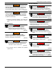
Unpacking and Inspection Generator Main Line Circuit Breaker Parts Shipped Loose See Figure 2-8. This is a 2-pole circuit breaker (generator disconnect) (A) rated according to relevant specifications. A B Indicator (B) Identifier—Green means OPEN or OFF. Red means CLOSED or ON. 006089 B A A Keys B Battery terminal cap C Owner’s and Installation manuals (not shown) D Wi-Fi manual (not shown) E Wi-Fi Quick Start Guide (not shown) 003585 Figure 2-8.
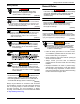
Site Selection and Preparation Section 3: Site Selection and Preparation Site Selection D 1.52 m (5 ft) B C E 1.52 m (5 ft) 0.91 m* (3 ft) 0.91 m* (3 ft) A B 0.91 m (3 ft) B F 005490 G D 001789 Figure 3-1. Installation Clearances ID Description Comments A Top of generator — B Front and end clearance Minimum clear distances cannot include shrubs, bushes, or trees. * See IMPORTANT NOTE on next page. C Rear clearance 45.
Site Selection and Preparation Install the generator set, in its protective enclosure, outdoors where adequate cooling and ventilating air is always available (Figure 3-1). Consider these factors: • The installation of the generator must comply strictly with ICC IFGC, NFPA 37, NFPA 54, NFPA 58, and NFPA 70 standards. • Install the unit where air inlet and outlet openings will not become obstructed by leaves, grass, snow, etc.
Site Selection and Preparation NOTE: See Figure 3-2. Southwest Research Institute testing approves 45.7 cm (18 in) installation minimum from structure (C). Southwest Research Institute is a nationally recognized third party testing and listing agency in the United States. The criteria was to determine the worst case fire scenario within the generator and to determine the ignitability of items outside the engine enclosure at various distances.
Site Selection and Preparation B A 000856 Figure 3-3. Compacted Soil or Gravel Pad NOTE: If a concrete pad is required, follow all applicable federal, state, or local codes. Transportation Recommendations Use a suitable cart or equipment to carry the generator, including the wooden pallet, to the installation site. Place cardboard between the hand cart and the generator to prevent any damage or scratches to the generator.
Generator Placement Section 4: Generator Placement Generator Placement See Figure 4-1. All air-cooled generators come with a non-sinking direct to dirt (DTD) composite base pad. The DTD pad elevates the generator and helps prevent water from pooling around the base. See Figure 4-2. Three mounting holes are available if codes require securing the generator to the concrete. The mounting holes are located inside the generator compartment—two at the front and one in back.
Generator Placement This page intentionally left blank.
Fuel Conversion / Gas Connections Section 5: Fuel Conversion / Gas Connections Fuel Requirements and Recommendations IMPORTANT NOTE: Use an approved pipe sealant or joint compound on all threaded fittings. NOTE: All installed gaseous fuel piping must be purged and leak tested prior to initial start-up in accordance with local codes, standards, and regulations. DANGER Explosion and fire. Fuel and vapors are extremely flammable and explosive. No leakage of fuel is permitted. Keep fire and spark away.
Fuel Conversion / Gas Connections Fuel Consumption Generator Natural Gas Propane 1/2 Load Full Load 1/2 Load Full Load 8 kVA 2.63 / 93 4.33 / 153 3.62 / 0.96 / 0.99 5.87 / 1.55 / 1.60 10 kVA 3.57 / 126 5.78 / 204 4.70 / 1.24 / 1.28 7.24 / 1.91 / 1.97 13 kVA 4.25 / 150 6.54 / 231 5.29 / 1.40 / 1.44 8.32 / 2.20 / 2.27 * Natural gas is in m3/h / ft3/h ** Propane is in L/h (LP) / gal/h (LP) / m3/h (LPV) *** Values given are approximate These are approximate values.
Fuel Conversion / Gas Connections Natural Gas Pipe Sizing NOTE: Add 0.76 m (2.5 ft) per any bend, tee, or angle in the pipe to the overall distance. Tables based on schedule 40 black pipe. If installing any other piping system, follow the pipe sizing charts for the selected piping system. To determine correct gas pipe size, find the kVA rating of the generator in the left column, and trace to the right.
Fuel Conversion / Gas Connections Installing and Connecting Gas Lines Flexible Fuel Line DANGER Explosion and fire. Fuel and vapors are extremely flammable and explosive. No leakage of fuel is permitted. Keep fire and spark away. Failure to do so will result in death or serious injury.
Fuel Conversion / Gas Connections Fuel Field Kit Installation (If Required) Overview Note 5—Provision of back-up hard-wired hardware safety systems can be used to reduce PES system SIL requirements as determined by the SIL analysis of the overall safety system. This procedure is for any installation that needs an externally controlled fuel shutoff to meet Australian agency requirements, specifically AS/NZS 3814-2015 clause 2.27.3(a)—Safety Systems. Table 5-3.
Fuel Conversion / Gas Connections Installation Instructions 170 mm (6.69 in) DANGER Automatic start-up. Disconnect utility power and render unit inoperable before working on unit. Failure to do so will result in death or serious injury. (000191) Throughout this procedure, refer to the Wire Gauge and Length Chart, the wiring diagram, the schematic diagram, and the splice diagram at the end of this section. 100 mm (3.94 in) 2X Ø 5 mm (0.20 in.
Fuel Conversion / Gas Connections 2. See Figure 5-5. Mount the DIN rail (A) to the drilled holes in the engine divider panel with two M4-0.7 X 10 (8-32 x 0.5 in) fasteners and nuts. Connect Wires 1. Wire control relays and timer relay per Wiring Diagram—AU Fuel Field Install Kit and Wire Gauge and Length Chart. 2. Connect kit wire Q to unit harness wire #86 by inserting and crimping the 6 mm stripped end of kit wire Q into the factory connected bullet connector hanging near the battery charger plug. 3.
Fuel Conversion / Gas Connections Wire Gauge and Length Chart Wire Number From—Connection 24 To—Connection Wire Length (mm) A Female Fast-On (14-16 Gauge) [Wires R & A intertwined] Female Fast-On (14-16 Gauge) [Wires D & A intertwined] 300 B Female Fast-On (18-20 Gauge) Female Fast-On (18-20 Gauge) 300 C Female Fast-On (18-20 Gauge) [Must fit male 4.75 mm x 0.5 mm] Female Fast-On (18-20 Gauge) 500 D Male Fast-On (18-20 Gauge) [Must fit female 4.75 mm x 0.
Fuel Conversion / Gas Connections Wiring Diagram—AU Fuel Field Install Kit Installation Guidelines For Australian 50 Hz Air-Cooled Generators 25
Fuel Conversion / Gas Connections Schematic Diagram—AU Fuel Field Install Kit 26 Installation Guidelines For Australian 50 Hz Air-Cooled Generators
Fuel Conversion / Gas Connections Splice Sheet—AU Fuel Field Install Kit Installation Guidelines For Australian 50 Hz Air-Cooled Generators 27
Fuel Conversion / Gas Connections Checking Gas Line Connections Perform Leak Test Check Gas Pressure 1. Check gas pressure at the regulator in the generator by following these steps. • Close gas supply valve. • See Figure 5-7. Remove the top gas pressure test port from the regulator and install the gas pressure tester (manometer). DANGER Explosion and fire. Fuel and vapors are extremely flammable and explosive. No leakage of fuel is permitted. Keep fire and spark away.
Fuel Conversion / Gas Connections Natural Gas Vapor Installation (typical) F B A C J G D E H L K 001808 NOTE: Fuel Field Kit not shown. Install according to local codes and regulations. NG Megajoules = m3/h X 37.
Fuel Conversion / Gas Connections LP Vapor Installation (typical) F G B C A D J K M E H L 001809 NOTE: Fuel Field Kit not shown. Install according to local codes and regulations. LP BTU = ft3/h X 2500 Megajoules = m3/h X 93.15 A BTU and pressure decal B Minimum distance from rear obstruction C Manual shutoff valve (pressure port optional) D Pipe nipple (field supplied) E Flexible fuel line F Check distance with gas provider. See Site Selection.
Electrical Connections Section 6: Electrical Connections Generator Connections See Figure 6-1. The electrical wiring enclosure is located behind an access panel on the intake end of the unit. Remove the intake side panel as directed in Intake Side Panel Removal, and then remove the access panel. Connect wires according to the diagram and tables. 1. Remove the main AC / control wiring knock-out plugs from the back of the generator. 2.
Electrical Connections Control Wiring C1 B A C2 E1 1 0 1 2 194 2 3 23 3 1 1 2 2 3 3 4 4 N1 N2 E2 T1 T2 005967 H D F G Figure 6-1. Electrical Wiring Connections Table 6-1.
Electrical Connections . Table 6-4. Ground and Neutral Connections (Copper or Aluminum Conductors) Common Alarm Relay (Option) No. Description Recommended Wire Size Torque Spec Alarms relating to generator and engine performance appear on the controller. The controller is equipped with a common alarm relay that provides contacts for an optional customer-supplied external alarm indicator. 1 Power wire terminal (E1) 2/0 to 8 AWG 13.
Electrical Connections NOTE: See Figure 6-2. Battery cables were factory connected at the generator. Connect cables to battery posts as follows: 4. Connect the red battery cable (A: from starter contactor) to the battery post indicated by a positive: POS or (+). Torque to 8 Nm (70 in-lbs). B A – Battery Disposal WARNING Environmental Hazard. Always recycle batteries at an official recycling center in accordance with all local laws and regulations.
Control Panel Start-Up/Testing Section 7: Control Panel Start-Up/Testing Control Panel Interface Generator Setup DANGER Automatic start-up. Disconnect utility power and render unit inoperable before working on unit. Failure to do so will result in death or serious injury. (000191) • Press the OFF mode button on the control panel, remove fuses, and disconnect battery cables to prevent accidental startup before performing any maintenance on the generator.
Control Panel Start-Up/Testing installation wizard will operate upon power restoration. The display will only prompt the customer for the current Time and Date. * This is required in addition to setting the fuel selector knob to the correct fuel for the generator to function properly. Table 7-1. Activation Chart Display Reads Language English Troubleshooting + Use arrow keys to scroll to desired language. Press ENTER to select. Language can be changed later using the EDIT menu.
Control Panel Start-Up/Testing Table 7-1. Activation Chart Display Reads Troubleshooting To Activate go to www.activategen.com 002229 If you do not have your activation code, go to www.activategen.com or call 1-8889ACTIVATE (922-8482 US & CA only). If you already have your activation code, wait 3–5 seconds for the next display. For international assistance, call 01262-953-5155. Use arrow keys to scroll and find the first number of your Activation Code. Press ENTER to select.
Control Panel Start-Up/Testing Cold Smart Start The Cold Smart Start feature is enabled at the factory, and can be disabled in the EDIT menu. When Cold Smart Start is enabled, the generator will monitor ambient temperature and adjust its warm-up delay accordingly. If the ambient temperature is below a fixed temperature upon startup in AUTO mode (per the chart below), the generator will warm up for 30 seconds, allowing the engine to warm before the load is applied.
Control Panel Start-Up/Testing Before starting, complete the following: 1. Verify generator is OFF. 2. Set the generator main circuit breaker to OFF (OPEN). 3. Turn OFF all breakers that will be powered by the generator. 4. Check the engine crankcase oil level and, if necessary, fill to the dipstick FULL mark with the recommended oil. Do not overfill. 5. Check the fuel supply. Gaseous fuel lines must have been properly purged and leak tested in accordance with applicable fuel-gas codes.
40 YES or NO Æ ENTER - 14 + * Select Hour (0-23) Å Cold Smart Start? Set Output Voltage 220, 230, 240 Fuel Selection + NG or LP - No + Yes or No - Setup Wi-Fi? ENTER + English + Espanol + Francais + Portuguese + ...... - Language Note: If language was previously programmed this goes directly to “Select Hour” Use UP and DOWN arrows. to select YES or NO. Press ENTER. Default voltage 220V. Use UP arrow to select output voltage and press ENTER.
Installation Guidelines For Australian 50 Hz Air-Cooled Generators ENTER SUB MENUS DATE/TIME * * Re-try using a higher quality USB drive. File names on the USB cannot have more than 8 characters. Possible Message(s): Corrupted File Invalid File File Not Found Unsupported Device* Switched to OFF Hours of Protection 0 (H) ENTER SETUP WIFI SYSTEM - 0 + Select Minute (0-59) ENTER ESC * ENTER ENTER * USB: V X.XX Current: V X.XX * Install Wizard Set Exercise...
Control Panel Start-Up/Testing Check Manual Transfer Switch Operation DANGER Electrocution. Do not manually transfer under load. Disconnect transfer switch from all power sources prior to manual transfer. Failure to do so will result in death or serious injury, and equipment damage. (000132) Refer to the Manual Transfer Operation section of the owner’s manual for procedures. Electrical Checks DANGER Electrocution. High voltage is present at transfer switch and terminals.
Control Panel Start-Up/Testing fuel issue. Check amperage value of loads and/or fuel pressure. 12. Let the generator run at full rated load for 20–30 minutes. Listen for unusual noises, vibration, or other indications of abnormal operation. Check for oil leaks, evidence of overheating, etc. 13. Verify gas pressure while under full load. Record loaded gas pressure: ______________. 14. When testing under load is complete, turn OFF electrical loads. 15.
Control Panel Start-Up/Testing This page intentionally left blank.
Troubleshooting Section 8: Troubleshooting Generator Troubleshooting Problem Engine will not crank Engine cranks but will not start Engine starts hard and runs rough Generator is set to OFF, but the engine continues to run No AC output from generator Cause Correction Blown fuse. Correct short circuit condition by replacing 7.5A fuse in generator control panel. Contact an IASD if fuse continues to blow. Loose, corroded, or defective battery cables. Tighten, clean, or replace as necessary.
Troubleshooting Problem No transfer to standby after utility source failure Unit consumes large amounts of oil Cause Correction MLCB (generator disconnect) is OFF (OPEN). Reset generator disconnect to ON (CLOSED). Defective transfer switch coil. Contact an IASD for assistance. Defective transfer relay. Contact an IASD for assistance. Transfer relay circuit open. Contact an IASD for assistance. Defective control logic board. Contact an IASD for assistance. Engine may be warming up.
Quick Reference Guide Section 9: Quick Reference Guide System Diagnosis To clear an active alarm, press the OFF mode button and then the ENTER button on the control panel. Then press the AUTO mode button. If the alarm reoccurs, contact an IASD. Table 9-1. System Diagnosis Active Alarm LED NONE FLASHING GREEN HIGH TEMPERATURE OVERLOAD REMOVE LOAD Problem Things to Check Check MLCB Unit running in AUTO but (generator no power in house. disconnect). Check MLCB. If it is ON, contact an IASD.
Quick Reference Guide Table 9-1. System Diagnosis (Continued) Active Alarm LED UNDERSPEED RED Unit will not start in AUTO with utility loss. Check the LEDs / Screen for alarms. Contact an IASD. STEPPER OVERCURRENT RED Unit will not start in AUTO with utility loss. Check the LEDs / Screen for alarms. Contact an IASD. MISWIRE RED Unit will not start in AUTO with utility loss. Check the LEDs / Screen for alarms. Contact an IASD. OVERVOLTAGE RED Unit will not start in AUTO with utility loss.
Accessories Section 10: Accessories Performance enhancing accessories are available for air-cooled generators. Accessory Cold Weather Accessories*— • Battery Pad Warmer Description • Recommended in areas where temperatures fall below -18 °C (0 °F). (Not necessary for use with AGM-style batteries) • Oil Warmer • Recommended in areas where temperatures fall below -18 °C (0 °F).
Accessories This page intentionally left blank.
Diagrams Section 11: Diagrams Installation Drawing (10000010257-B—1 of 2) MOUNTING TO CONCRETE PAD HOLE LOCATIONS FOR OPTIONAL MOUNTING TO A CONCRETE PAD 521 [20.5] 16 [5/8] DIA. CLEARANCE HOLE (3) PLACES, 10 [3/8] DIA. MASONRY ANCHOR BOLTS RECOMMENDED 68 [2.7] 197 [7.7] 457 [17.9] FRONT OF UNIT MAIN AC/CONTROL WIRING HOLE FOR 1 1/4" CONDUIT MAIN AC/CONTROL WIRING HOLE FOR 3/4" CONDUIT ( -REMOVE FACTORY PLUGS AND DISCARD -CLOSE ANY UNUSED HOLE WITH A NEMA 3R RATED PLUG (FIELD SUPPLIED) 393 [15.
Diagrams Installation Drawing (10000010257-B—2 of 2) AIR INTAKE 457 [18.0] MINIMUM OPEN AREA 914 [36.0] MINIMUM OPEN AREA AIR INTAKE AIR OUTLET 914 [36.0] MINIMUM OPEN AREA TOP VIEW 914 [36.0] MINIMUM OPEN AREA "DO NOT LIFT BY ROOF" LIFTING HOLES 4 CORNERS: 30 [ 1.2] - MUST BE LIFTED WITH STEEL RODS - RECOMMENDED LIFTING ROD SIZE: 25 [ RIGHT VIEW INTAKE PANEL REMOVED 1.0] 1218 [48.0] 127 [5.0] GRAVEL PAD/ COMPACTED SOIL 52 1232 [48.
REVISION: A DATE: 06/15/18 Installation Guidelines For Australian 50 Hz Air-Cooled Generators INTERCONNECTION DIAGRAM RXS UNSWD NEUT XFRSW INTERCON 50HZ AU/NZ DRAWING #: 10000038913 GROUP G Diagrams Interconnection Drawing (10000038913-A) 53
Diagrams Wiring Diagram (10000008280-G—1 of 6) 54 Installation Guidelines For Australian 50 Hz Air-Cooled Generators
Diagrams Wiring Diagram (10000008280-G—2 of 6) Installation Guidelines For Australian 50 Hz Air-Cooled Generators 55
Diagrams Wiring Diagram (10000008280-G—3 of 6) 56 Installation Guidelines For Australian 50 Hz Air-Cooled Generators
Diagrams Wiring Diagram (10000008280-G—4 of 6) Installation Guidelines For Australian 50 Hz Air-Cooled Generators 57
Diagrams Wiring Diagram (10000008280-G—5 of 6) 58 Installation Guidelines For Australian 50 Hz Air-Cooled Generators
Diagrams Wiring Diagram (10000008280-G—6 of 6) Installation Guidelines For Australian 50 Hz Air-Cooled Generators 59