Owner’s Manual For Diesel Generator MLG8 • MLG15 • MLG20 • MLG20ICAN MODEL NUMBER: _________________________ SERIAL NUMBER: _________________________ DATE PURCHASED:________________________ Register your Generac product at: WWW.GENERAC.
WARNING California Proposition 65. Engine exhaust and some of its constituents are known to the state of California to cause cancer, birth defects, and other reproductive harm. (000004) WARNING California Proposition 65. This product contains or emits chemicals known to the state of California to cause cancer, birth defects, and other reproductive harm.
Table of Contents Introduction and Safety Introduction .......................................................1 Read This Manual Thoroughly ..........................1 Safety Rules ......................................................1 General Hazards ...............................................2 Explosion and Fire Hazards ..............................2 Trailer Hazards ..................................................3 Electrical Hazards .............................................
This page intentionally left blank.
Introduction and Safety Section 1 Introduction and Safety Introduction Thank you for purchasing a Generac Mobile Products LLC product. This unit has been designed to provide high-performance, efficient operation, and years of use when maintained properly. The information in this manual is accurate based on products produced at the time of publication. The manufacturer reserves the right to make technical updates, corrections, and product revisions at any time without notice.
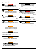
Introduction and Safety General Hazards CAUTION DANGER Asphyxiation. Running engines produce carbon monoxide, a colorless, odorless, poisonous gas. Carbon monoxide, if not avoided, will result in death or serious injury. (000103) Equipment or property damage. Do not block air intake or restrict proper air flow. Doing so could result in unsafe operation or damage to unit. (000229) Explosion and Fire Hazards WARNING Hearing Loss. Hearing protection is recommended when using this machine.
Introduction and Safety Trailer Hazards Electrical Hazards WARNING Trailer must be securely coupled to the hitch and chains correctly attached. Uncoupled or unchained towing could result in death or serious injury. (000233) WARNING Do not operate this unit while transporting. Doing so could result in death or serious injury. (000231) WARNING Crushing hazard. Verify unit is properly secured and on level ground. An unsecured unit can suddenly roll or move, causing death or serious injury.
Introduction and Safety Battery Hazards DANGER Electrocution. Do not wear jewelry while working on this equipment. Doing so will result in death or serious injury. (000188) WARNING (000137a) WARNING Explosion. Do not dispose of batteries in a fire. Batteries are explosive. Electrolyte solution can cause burns and blindness. If electrolyte contacts skin or eyes, flush with water and seek immediate medical attention. (000162) WARNING Risk of burn. Do not open or mutilate batteries.
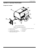
General Information Section 2 General Information Component Locations B A C D E H G F Figure 2-1. Component Locations Table 2-1.
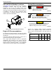
General Information Unit and Serial Number Locations Coolant Recommendation See Figure 2-2 to locate the unit ID tag (A) and Vehicle Identification Number (VIN) tag (B). Important information, such as the unit model number, serial number, VIN and tire loading information is found on these tags. Record the information from these tags so it is available if the tags are lost or damaged. When ordering parts or requesting assistance, you may be asked to provide this information. DANGER Risk of poisoning.
General Information Main Control Panels B A C 240VAC MAIN CIRCUIT BREAKER D I ON ON O TURN MAIN BREAKER OFF I 120VAC BREAKER 120VAC BREAKER 20 20 E GLOW PLUG INDICATOR OFF GLOW PLUGS RUN START 240VAC BREAKER 120VAC 120VAC H I ON ON F O 240VAC 0 0 0 0 0 HOURS G NEUTRAL BONDED TO FRAME B F MLG8 MAIN BREAKER 240V A ON 0 0 0 0 0 ON HOURS D E TURN MAIN BREAKER OFF OFF GLOW PLUG RUN START NEUTRAL BONDED TO FRAME MLG15 • MLG20 • MLG20ICAN Figure 2-3.
General Information This page intentionally left blank.
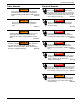
Operation Section 3 Operation Prestart Checklist Starting the Unit Before starting the unit, all items in the prestart checklist must be completed. DANGER Asphyxiation. Running engines produce carbon monoxide, a colorless, odorless, poisonous gas. Carbon monoxide, if not avoided, will result in death or serious injury. (000103) WARNING Consult Manual. Read and understand manual completely before using product. Failure to completely understand manual and product could result in death or serious injury.
Operation 3. See Figure 3-2. As soon as it is glowing, turn the key to START (A) and hold it until the engine cranks and starts running. Emergency Stop Switch WARNING In case of an emergency, press the emergency stop button to stop the engine immediately. Failure to do so could result in death or serious injury. (000298) CAUTION A Equipment Damage. The emergency stop switch is not to be used to power down the unit under normal operating circumstances. Doing so will result in equipment damage.
Operation Voltage Regulator This unit is equipped with an electronic voltage regulator. The voltage regulator controls the output of the generator by regulating the current into the exciter field. The regulator has three screwdriver adjustable potentiometers that may be adjusted for voltage, stability and voltage roll-off (U/F). The voltage regulator is adjusted before shipment from the factory. Contact Generac Mobile Products for additional information before attempting to adjust the voltage regulator.
Operation 6. Check the wheel lugs. Tighten or replace any lugs that are loose or missing. If a tire has been removed for axle service or replaced, tighten the lugs, in the order shown, to the following specifications: a. Start all lug nuts by hand. b. First pass tighten to 20-25 ft-lbs (27-33 Nm). c. Second pass tighten to 50-60 ft-lbs (67-81 Nm). d. Third pass tighten to 90-120 ft-lbs (122-162 Nm). Use the forklift pockets with care.
Maintenance Section 4 Maintenance Emissions Information For emissions information, see the OEM engine manual. Daily Walk Around Inspection CAUTION Equipment Damage. Failure to perform a daily inspection could result in damage to the unit. (000306) Look for conditions that could hinder performance or safety, such as (but not limited to) oil/coolant/fuel leakage, blocked vents, loose/missing hardware, and electrical connections.
Maintenance Table 4-1.
Maintenance Table 4-3.
Maintenance Jack Maintenance The following procedures should be performed annually. Side-Wind Models • The internal gearing and bushings of the jack must be kept lubricated. Apply a small amount of automotive grease to the internal gearing by removing the jack cover, or if equipped, use a needle nose applicator or standard grease gun on the lubrication point found on the side of the jack near the crank. Rotate the jack handle to distribute the grease evenly.
Maintenance Lower Radiator Hose Heater Option Use and Maintenance WARNING Personal Injury. Do not modify the location of the lower radiator hose heater. Improper use of hose heater could result in personal injury or engine damage. (000339) The following points should be followed when operating a unit equipped with a lower radiator hose heater. • Verify the cooling system is full of the proper mixture of water and engine coolant before each heater use.
Maintenance This page intentionally left blank.
Owner’s Manual for Mobile Generator BLK BLK RED RED BLK BLK RED RED GRN 50 AMP TWIST LOCK RECEPTACLE RED GRN 30 AMP TWIST LOCK RECEPTACLE RED GRN 30 AMP TWIST LOCK RECEPTACLE 50 AMP CIRCUIT BREAKER BLK BLK 30 AMP CIRCUIT BREAKER BLK WHT 30 AMP CIRCUIT BREAKER 2 1 BONDED TO GROUND GRN 50 AMP TWIST LOCK RECEPTACLE 50 AMP CIRCUIT BREAKER 4 3 WHT WHT 5 6 7 8 9 10 GRN/YEL RED 20 AMP G.F.I. RECEPT.
20 BLK RED WHT RED GRN WHT TO GROUND GRN BLK BLK RED RED BLK BLK RED RED TO MAIN BREAKER BLK BLK BLK RED RED RED BLK BLK GRN RED GRN BLK RED GRN BLK RED GRN WHT GRN 240 VOLT 30 AMP TWIST-LOCK RECEPTACLE 30 AMP CIRCUIT BREAKER 2x5-20R, 4xL14-30R GRN 240 VOLT 30 AMP TWIST-LOCK RECEPTACLE WHT WHT WHT 2x5-20R, 3xL14-30R, 1x50A TO NEUTRAL WHT GRN WHT 240 VOLT 50 AMP TWIST-LOCK RECEPTACLE RED 240 VOLT 30 AMP TWIST LOCK RECEPTACLE 90319_ORG_07.06.
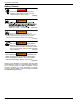
Wiring Diagrams and Service Log AC Wiring Diagram - MLG 8 TERMINAL BLOCK 1 RED 10 RED BLK MAIN CIRCUIT BREAKER 40 AMP 2 POLE 8 BLK 7 6 RED 5 L2 L1 WHT 4 WHT 3 WHT GRN RED 9 2 GEN 1 GRN/YEL 20 AMP G.F.I. OUTLET CB 240 VOLT 30 AMP CIRCUIT BREAKER 240 VOLT 30 AMP TWIST LOCK RECEPTACLE GRN 20 AMP CIRUIT BREAKER 20 AMP G.F.I. OUTLET CB GRN 20 AMP CIRUIT BREAKER 90732_A_07.25.
Wiring Diagrams and Service Log DC Wiring Diagram - MLG 8 and MLG15 TERMINAL BLOCK 1 RED 10 RED BLK MAIN CIRCUIT BREAKER 40 AMP 2 POLE 8 BLK 7 6 RED 5 L2 L1 WHT 4 WHT 3 WHT GRN RED 9 2 GEN 1 GRN/YEL 20 AMP G.F.I. OUTLET CB 240 VOLT 30 AMP CIRCUIT BREAKER 240 VOLT 30 AMP TWIST LOCK RECEPTACLE GRN 20 AMP CIRUIT BREAKER 20 AMP G.F.I. OUTLET CB GRN 20 AMP CIRUIT BREAKER 90732_A_07.25.
Owner’s Manual for Mobile Generator WARNING LIGHT “TURN MAIN BREAKER OFF” RED 4 RED GRN S B BATTERY 12V RED EMERGENCY STOP SWITCH 3 VIO ACC N.C. N.C.
24 LEFT TAIL/TURN LAMP RED MARKER LAMP AMBER MARKER LAMP BK BK BK BK WT BK RD WT SPLICE SPLICE SPADE SPADE SPADE BN WT WT BN SPADE SPADE LICENSE PLATE LAMP BK YL WT BN BN TRAILER PLUG GN RING WT SPLICE SPADE SPADE BN WT BK RD WT SPLICE SPLICE BK BK BK BK RIGHT TAIL/TURN LAMP RED MARKER LAMP AMBER MARKER LAMP Wiring Diagrams and Service Log Trailer Harness WT BN YL GN 90341_B_12.20.
Wiring Diagrams and Service Log Service Log OIL GRADE: _____________________________________ BRAND: __________________________________ COOLANT MIXTURE: _____________________________ BRAND: __________________________________ __________________________________________________________________________________________ __________________________________________________________________________________________ __________________________________________________________________________________________ _____________
Wiring Diagrams and Service Log This page intentionally left blank.
Part No. 10289 Rev. M 09/09/16 ©2016 Generac Mobile Products LLC. All rights reserved Specifications are subject to change without notice. No reproduction allowed in any form without prior written consent from Generac Mobile Products LLC. Generac Mobile Products 215 Power Drive, Berlin, WI 54923 GeneracMobileProducts.