Owner’s Manual Power Grader 006100 MODEL NUMBER: _________________________ SERIAL NUMBER: _________________________ DATE PURCHASED:________________________ Register your Generac product at: WWW.GENERAC.
WARNING Operating, servicing and maintaining this equipment can expose you to chemicals including engine exhaust, carbon monoxide, phthalates, and lead, which are known to the State of California to cause cancer and birth defects or other reproductive harm. To minimize exposure, avoid breathing exhaust, do not idle the engine except as necessary, service your equipment in a well-ventilated area and wear gloves or wash your hands frequently when servicing your equipment. For more information go to www.
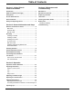
Table of Contents Section 1: Safety Rules & General Information Section 4: Maintenance and Troubleshooting Introduction ..................................................................1 Maintenance ...............................................................17 Read This Manual Thoroughly ....................................1 Maintenance Schedule ..............................................17 Safety Rules .................................................................1 Replacing Tooth Bar ...
This page intentionally left blank.
Safety Rules & General Information Section 1: Safety Rules & General Information Introduction Thank you for purchasing a Generac Power Systems Inc. product. This unit has been designed to provide high performance, efficient operation, and years of use when maintained properly. The information in this manual is accurate based on products produced at the time of publication. The manufacturer reserves the right to make technical updates, corrections, and product revisions at any time without notice.
Safety Rules & General Information General Hazards WARNING WARNING Accidental Start-up. Disconnect the negative battery cable, then the positive battery cable when working on unit. Failure to do so could result in death or serious injury. (000130) WARNING Risk of injury. Do not operate or service this machine if not fully alert. Fatigue can impair the ability to service this equipment and could result in death or serious injury. (000215) WARNING Personal injury. Keep out of reach of children.
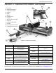
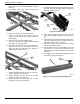
General Information and Setup Section 2: General Information and Setup E D A Tow Hitch F B Pitch Adjust Assembly C Height Adjust Cables D Actuator E Fuse F Battery C G Actuator Cover H Mold Bar I Axle and Wheel Assembly J Tooth Bar G K Actuator Wire Harness I H L Tow Bar M Control Box Wire Harness N Height Adjust Control Box B A L K J 0060100 M N Figure 2-1. Features and Controls Table 1 – Specifications Teeth 14 ea.
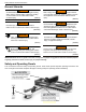
General Information and Setup Remove Contents from Carton Hardware Bag 1. See Table 2-2. Remove and verify carton contents prior to assembly. Carton contents should contain: A B C E D G F H Main Parts I A H B U X Y C E K J G W F D V 006101 T Figure 2-2. Main Parts Item P Description A QTY Tow Bar 1 B Pitch Bar 1 C Tongue Bar 1 D Ball Hitch 1 E Axle 1 Q O N M L 006103 Figure 2-4.
General Information and Setup Manual Caddy 7. See Figure 2-7. Secure each strap with a 3/8-16 X 2-1/2" bolt with 3/8" flat washer, rail spacer (D), and locknut with 3/8” washer using two 9/16" wrenches. D B A C D 006101 Figure 2-5. Manual Caddy Item Description QTY A Manual Caddy 1 B Washer, Flat, 5/16” USS 4 C Nut, Nylon Lock 5/16”-18 LP 2 D Bolt, HCS, 5/16”-18X3, GR5, ZP 2 006142 Figure 2-7. Rail Spacers 8. Tighten all weight box strap hardware. 9. See Figure 2-8.
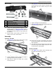
General Information and Setup 2. Place tow bar (B) under crossmembers (A) and align tow bar holes with crossmember mounting holes (C). 3. See Figure 2-10. Insert tooth bar bracket (D) between tow bar and tooth bar. Installing Pitch Plate 1. See Figure 2-12. Place adjust pitch plate (A) to the left front of tow bar and align holes in adjust pitch plate with holes in tow bar. B E A F C D D 006108 006143 Figure 2-10. Tow Bar Assembly Figure 2-12. Pitch Plates 4.
General Information and Setup 7. See Figure 2-14. Secure pitch bar to pitch plates with pitch bar pin and hair pin cotter pin with 81" ID X 1.5"OD X .11" washer (G). G Ball Hitch Install 1. See Figure 2-16. Install ball hitch (A) onto tongue bar (B) with two 1/2-13 X 3.25" bolts with 1/2" washers and two 1/2” locknuts with 1/2" washers (C) using two 3/4" wrenches. A B 006110 Figure 2-14. Pitch Bar D Pin Hitch Install 006112 Figure 2-16. Ball Hitch Installation 1. See Figure 2-15.
General Information and Setup 5. See Figure 2-18. Install axle (E) to both axle brackets (D) with 1/2 X 3/8L, 3/8-16 shoulder bolts with 3/8” washers and 3/8" locknuts with 3/8” washers using a 4mm Allen wrench and 9/16" wrench. Installing Actuator 1. See Figure 2-21. Loosen hand knobs (A) securing actuator cover (B) and remove cover. B D E A 006114 Figure 2-18. Axle Installation NOTE: See Figure 2-19.
General Information and Setup 6. Reinstall battery with battery strap and wing nuts. 7. See Figure 2-24. Route height adjust cables (H) through the gaps between front crossmember and tooth bar (I) and rear crossmember and mold bar (J). 10. See Figure 2-27. Install outer nut (Q) and tighten with 1/2” wrench while holding inner nut with 1/2” wrench. I Q J R 006124 Figure 2-27. Inserting Cable Through Axle Bracket H 006119 Figure 2-24. Actuator Assembly on Frame 8. See Figure 2-25.
General Information and Setup Installing Actuator Harness 1. See Figure 2-30. Insert actuator harness (A) into Molex mount (B) and push to snap in place. 7. Continue routing harness until there is no slack at tow bar. 8. See Figure 2-33. Connect two actuator plugs (K) to harness. M L B C D K A 006125 006128 Figure 2-30. Molex Mount Figure 2-33. Actuator Plugs 2. Plug extension harness (C) into actuator harness at Molex mount. 3. Plug control box (D) onto extension harness. 4. See Figure 2-31.
General Information and Setup Attaching Manual Caddy 1. See Figure 2-36. Place manual caddy on tow bar and align the caddy mounting holes with tow bar mounting holes. A Connecting Power Grader to Tow Vehicle Verify power grader frame is level before connecting power grader to tow vehicle. If frame is not level, see Adjusting Pin Hitch Position for instructions on adjusting tow bar height. Lawn Tractor Tow Bar Hitch 1. Stop lawn tractor engine and set parking brake. 2. See Figure 2-37.
General Information and Setup This page intentionally left blank 12 Owner’s Manual for Power Grader
Operation Section 3: Operation Operation and Use Questions WARNING Personal injury. Using grader for other than intended purposes of grading could result in death, serious injury, or equipment damage. (000478) Contact Generac Customer Service at 1-888-436-3722 (1-888-GENERAC), or www.generac.com with questions or concerns about unit operation and maintenance. Operating Parameters WARNING WARNING Personal injury.
Operation Adjusting Tooth Bar Height • Push control box toggle switch to LOWER position (A) to lower tooth bar for grading. • Push toggle switch to RAISE position (B) to raise tooth bar from work for turning around or leaving work area. A 3. Remove the front bolt, Molex mount, washers and locknut (C). 4. See Figure 3-3. Flip pitch plate assembly over and reinstall bolts, washers, Molex mount, and locknuts. 5. For further adjustments, pull pull pin (D) to disengage pin from pitch plate.
Operation Adjusting Mold Board Proceed as follows to convert molding board from one edge to the other. Adjusting Mold Board Angle The mold board can be adjusted to three different angles to provide for varying degrees of aggressiveness. 1. See Figure 3-6. Remove bolts and locknuts (A) securing both mold board ends to power grader frame using two 9/16" wrenches. See Figure 3-5. Set the mold board at rearmost hole (A) for aggressive grading. Use forward positions (B) for a smoother surface.
Operation This page intentionally left blank 16 Owner’s Manual for Power Grader
Maintenance and Troubleshooting Section 4: Maintenance and Troubleshooting Maintenance Regular maintenance will improve performance and extend engine/equipment life. Regular maintenance, replacement, or repair of the emissions control devices and systems may be performed by any repair shop or person of the owner’s choosing. To obtain emissions control warranty service free of charge, contact your nearest authorized dealer, or contact Generac Customer Service at 1-888-436-3722 (1-888GENERAC), or www.
Maintenance and Troubleshooting Battery Care Charging the Battery WARNING Explosion. Batteries emit explosive gases while charging. Keep fire and spark away. Wear protective gear when working with batteries. Failure to do so could result in death or serious injury. (000137a) WARNING If the battery loses charge, use a trickle charger to charge it. The charger must have an output of 14.4-15 volts at no more than 0.69 amps. Proceed as follows to connect the battery to a battery charger. 1.
Maintenance and Troubleshooting Troubleshooting Symptom Possible Cause Teeth set too low. Raise tooth bar height. The tow vehicle wheels spin during grading Too much additional weight. Remove weight. Tow vehicle power is inadequate for application Tow bar angle is not set correctly. Adjust tow bar up for better grading or adjust the bar down for better scarifying. The teeth are not digging properly Wheels are not lifted all the way up. Raise wheels. Not enough weight for hardness of surface material.
Part No. 10000024613 Rev. A 02/26/2018 ©2018 Generac Power Systems, Inc. All rights reserved Specifications are subject to change without notice. No reproduction allowed in any form without prior written consent from Generac Power Systems, Inc. Generac Power Systems, Inc. S45 W29290 Hwy. 59 Waukesha, WI 53189 1-888-GENERAC (1-888-436-3722) www.generac.