
Replacement Part List
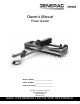


6 Owner’s Manual for Power Grader
General Information and Setup
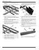
2. Place tow bar (B) under crossmembers (A) and
align tow bar holes with crossmember mounting
holes (C).
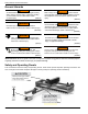
3. See Figure 2-10. Insert tooth bar bracket (D)
between tow bar and tooth bar.
Figure 2-10. Tow Bar Assembly
4. Secure tow bar to front crossmember with
1/2-13 X 7" bolt with 1/2" flat washer, center rail
spacer, and 1/2" locknut with 1/2” flat washer (E).
Finger tighten.
5. Secure tow bar to tooth bar bracket with
3/8-16 X 3" bolt with 3/8" washer and locknut with
3/8” washer (F). Finger tighten.
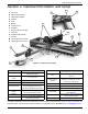
6. See Figure 2-11. Secure the rear of tow bar with
1/2-13 X 4.5" bolt with 1/2" washer, center rail
spacer (J), and 1/2" locknut with 1/2” washer (I).
Tighten with two 3/4" wrenches.
Figure 2-11. Tow Bar Assembly
7. Tighten hardware securing tow bar to front cross-
member using two 3/4” wrenches.
8. Tighten hardware securing tow bar to tooth bar
bracket using two 9/16” wrenches.
9. Tighten hardware securing tooth bar to frame
assembly with two 9/16” wrenches.
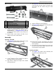
Installing Pitch Plate
1. See Figure 2-12. Place adjust pitch plate (A) to the
left front of tow bar and align holes in adjust pitch
plate with holes in tow bar.
Figure 2-12. Pitch Plates
2. Place pitch plate (B) to right front of tow bar and
align holes in adjust pitch plate with holes in tow
bar.
3. Install 3/8-16 X 3" bolt with 3/8" washer and locknut
with 3/8” washer through rear mounting holes (C)
and tighten with two 9/16" wrenches.
4. Align hole in Molex mount (D) with front mounting
hole in the adjust pitch plate.
5. Secure Molex mount and pitch plates to tow bar
with 3/8-16 X 3" bolt with 3/8" washer and 3/8”
locknut with 3/8" washer and tighten with two 9/16"
wrenches.
6. See Figure 2-13. Install pull pin assembly (E) onto
pitch bar (F) using a 7/8" wrench.
Figure 2-13. Pull Pin Assembly and Pitch Bar
006143
F
D
E
006107
J
I
006108
A
B
C
D
006109
F
E