
Replacement Part List


Owner’s Manual for Power Grader 7
General Information and Setup
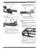
7. See Figure 2-14. Secure pitch bar to pitch plates
with pitch bar pin and hair pin cotter pin with
81" ID X 1.5"OD X .11" washer (G).
Figure 2-14. Pitch Bar
Pin Hitch Install
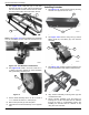
1. See Figure 2-15. Insert hitch clevis pin (A) into pin
hitch strap (B) and tongue bar (C)
Figure 2-15. Pin Hitch Installation
2. Secure pin hitch strap onto tongue bar with two
3/8-16 X 3" bolts with 3/8" washers and two 3/8”
locknuts with 3/8” washers (D) using two 9/16"
wrenches.
3. Secure tongue bar to pitch bar with hitch clevis pin
and hairpin cotter pin with 1/2” washer (E).
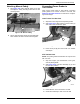
Ball Hitch Install
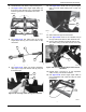
1. See Figure 2-16. Install ball hitch (A) onto tongue
bar (B) with two 1/2-13 X 3.25" bolts with
1/2" washers and two 1/2” locknuts with 1/2" wash-
ers (C) using two 3/4" wrenches
.
Figure 2-16. Ball Hitch Installation
2. Secure tongue bar to pitch bar with hitch clevis pin
and hairpin cotter pin with 1/2” washer (D).
Installing Axle Mounting Bracket and Wheel
Assemblies
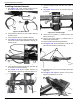
1. See Figure 2-17. Align top and rear holes of axle
mounting bracket (A) with top and rear holes in
rear crossmember.
2. Secure the top of axle mounting bracket onto rear
crossmember with 3/8-16 X 2-1/2" bolt with 3/8"
washer, rail spacer and 3/8” locknut with 3/8"
washer (B) using two 9/16" wrenches.
Figure 2-17. Axle Mounting Bracket
3. Secure rear of axle mounting bracket to cross-
member (C) with 3/8-16 X 3/4" bolts with 3/8"
washers and 3/8” locknuts with 3/8" washers using
two 9/16" wrenches.
4. Repeat steps 1-3 with the second axle mounting
bracket, installing the bracket to the rear cross-
member in the holes provided on the other side.
006110
G
006111
B
A
C
D
E
006112
A
D
B
C
006113
A
B
C