
Replacement Part List


8 Owner’s Manual for Power Grader
General Information and Setup
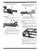
5. See Figure 2-18. Install axle (E) to both axle
brackets (D) with 1/2 X 3/8L, 3/8-16 shoulder bolts
with 3/8” washers and 3/8" locknuts with 3/8” wash-
ers using a 4mm Allen wrench and 9/16" wrench.
Figure 2-18. Axle Installation
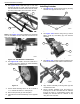
NOTE: See Figure 2-19. Axle weldment and hardware
must be orientated as show with bolt and axle arm on
right side of bracket.
Figure 2-19. Axle Weldment and Hardware
6. See Figure 2-20. Install a .81" ID X 1.5"OD X .11"
L washer onto axle, followed by wheel assembly
with grease fitting (F) facing out.
Figure 2-20. Wheel Assembly
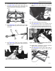
7. Secure wheel assembly with a .81" ID X 1.5"OD X
.11" L washer and 3/32 X 1" cotter pin (G).
8. Bend cotter pin ends (H) over with pliers.
9. Install the second wheel assembly on the opposite
side.
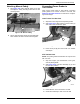
Installing Actuator
1. See Figure 2-21. Loosen hand knobs (A) securing
actuator cover (B) and remove cover.
Figure 2-21. Actuator Cover and Hand Knobs
2. See Figure 2-22. Remove wing nuts (C) and lift
battery strap (D) and battery (E) from actuator
assembly.
Figure 2-22. Battery Strap Wingnuts
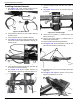
3. See Figure 2-23. Position actuator assembly onto
frame crossmembers with cables toward the front.
Figure 2-23. Actuator Assembly on Frame
4. Align actuator assembly mounting holes (G) with
crossmember holes.
5. Secure actuator assembly from the bottom by
inserting four 1/4-20 X 3/4" bolts with 1/4" washers
through the holes in crossmember bottom and
installing 1/4" locknuts with 1/4” washers on top
using two 7/16” wrenches.
006114
D
E
006666
006145
G
F
H
006113
B
A
006117
D
E
C
006118
G