Owner’s Manual Light Tower PLT240 LINK Tower STOP DETAIL C 002994 For technical assistance contact: www.generacmobileproducts.
Use this page to record important information about your Light Tower Unit Model Number Unit Serial Number Record the information found on your unit data label on this page. See unit serial number location (Unit Serial Number Locations). The data plate is affixed to the mast inside the cabinet. When contacting an Generac Mobile Products Authorized Dealer about parts and service, always supply the complete model number and serial number of the unit.
Table of Contents Section 1: Introduction and Safety Section 4:Maintenance Introduction ..........................................................1 Daily Walk-Around Inspection ......................... 17 Read This Manual Thoroughly ....................................1 General Maintenance ........................................ 17 How to Obtain Service .................................................1 Preparing for Service .................................................17 Safety Rules ........
Table of Contents This page intentionally left blank.
Introduction and Safety Section 1: Introduction and Safety Introduction Safety Rules Thank you for purchasing a Generac Mobile Products LLC product. This unit has been designed to provide high performance, efficient operation, and years of use when maintained properly. The manufacturer cannot anticipate every possible circumstance that might involve a hazard. The warnings in this manual, and on tags and decals affixed to the unit are, therefore, not all inclusive.
Introduction and Safety General Hazards Electrical Hazards DANGER WARNING Moving Parts. Keep clothing, hair, and appendages away from moving parts. Failure to do so could result in death or serious injury. (000111) Electrocution. In the event of electrical accident, immediately shut power OFF and disconnect unit from source. Use non-conductive implements to free victim from live conductor. Apply first aid and get medical help. Failure to do so will result in death or serious injury.
Introduction and Safety Starting the Unit • DO NOT wash the unit with high pressure hoses, power washers, or steam cleaners. Water may collect in the unit, causing damage to electrical parts. DANGER • Replace all missing and hard to read decals. Decals Electrocution. DO NOT use the unit if electrical cord is cut or worn through. Doing so will result in death or serious injury. (000263a) provide important operating instructions and warn of dangers and hazards.
Introduction and Safety 9 1 2 2 3 8 4 7 7 5 > 45 mph TM SET UP AUFSTELLUNG INSTALACIÓN INSTALLATION 1ST 15A 20A 15A 6 20A + 2ND 20A 15A 003686 Figure 1-1.
General Information Section 2: General Information Specifications DESCRIPTION UNITS PLT240-LED lbs (kg) 558 (252.6) Lighting Type — Light-Emitting Diode (LED) LED Driver — (4) Mean Well HLG-320H-30A Lumens — 88,000 Circuit Breaker Size amperes 15A / 20A Main Breaker Amperage Selection amperes 15A / 20A 120V-20 amp GFCI Receptacle quantity 1 Power Selection Switch quantity 1 120V-20 amp Twist Lock Inlet quantity 1 120V-15 amp Inlet quantity 1 quantity 1 Tire Size in.
General Information Unit Serial Number Locations See Figure 2-1 to locate the unit ID tag on the unit. Important information, such as the unit serial number, model number, and tire loading information are found on these tags. Record the information from these tags so it is available if the tags are lost or damaged. When ordering parts or requesting assistance, you may be asked to provide this information.
General Information Unit Dimensions B A C F E D 003440 Figure 2-2. Unit Dimensions PLT240 A B C D E F 54 in. (1.37 m) 77.5 in. (1.96 m) 16 ft. (4.88 m) 31.5 in. (0.80 m) 57 in. (1.45 m) 74 in. (1.88 m) Specifications are subject to change without notice.
General Information Component Locations F L K G J E I C H D B A 003443 Figure 2-3. Component Locations—Front and Left Side A. B. C. D. E. F. 8 Forklift pockets / tie-down locations Swiveling caster (lockable) Control panel Water Protection Shield Quick start guide LED fixtures (4) G. H. I. J. K. L.
General Information Control Panel IMPORTANT NOTE: If the control panel is ever removed, replace the gasket behind control panel and the gasket between the water ingress cover and control panel. B C D A ON ON 1 2 3 OFF 15A 4 E OFF 20A G 15A IN 20A IN 20A OUT F 003389 Figure 2-4. Control Panel Control Panel Components and Functions (E) 120VAC/20A GFCI convenience receptacle (5-20R) Resettable main circuit breaker for the LED lights and 120V/20A GFCI receptacle.
General Information Internal Storage See Figure 2-6. The interior of the cabinet can be used for storing nonflammable items such as shore power cords, small equipment, or tools when the unit is not in operation. Locking doors (A) on each side of the cabinet provide access to the cabinet interior. NOTE: Cabinet is not waterproof. 4. Close and lock both access doors and the control panel. 5. See Figure 2-6.
General Information See Figure 2-8. The chassis is equipped with a swiveling caster at the rear. Step on the brake (E) to lock the caster and prevent the wheel from rotating. Raise the brake to unlock the caster. E 003515 Figure 2-8. Swiveling Caster Tying the Unit Down When securing the unit for transportation, verify the equipment being used to fasten the unit is in good condition and has sufficient strength to hold the unit in place during transport. See Figure 2-6.
General Information This page intentionally left blank.
Operation Section 3: Operation Operation Configuration Before setting up the unit, determine if the unit will operate as a standalone light tower, or if export power will be required. If the unit will be operated as a standalone light tower, either the 120V-15A or 120V-20A input power plugs can be used. If export power is required, or a second link tower will be connected (via the 120V GFCI receptacle), 120V-20A input power is required.
Operation A B STOP A DETAIL C C 003544 Figure 3-1. Set Up Outriggers and Jacks B 7. Rotate each jack handle clockwise to start leveling the unit. Adjust all four jacks by rotating their handles clockwise until the wheels and caster are not touching the ground. 8. Before raising the mast, it may be necessary to adjust the LED fixtures. The LED fixtures may be adjusted up, down, left or right by simply aiming them in the desired direction. Raising the Mast 002994 1. Set up and level the unit.
Operation WARNING Personal Injury. Stop immediately if the mast hangs up or the winch cable develops slack. Excess slack could cause the mast to collapse, resulting in personal injury or equipment damage. (000265) IMPORTANT NOTE: Contact a Generac Mobile Products Authorized Dealer immediately if the mast hangs up or the winch cable develops slack. NOTE: Over-extension of the mast can lead to overtensioning of the mast cable. Do not extend the mast beyond the colored mark on the second mast section.
Operation Long-Term Storage Perform the following steps if the machine is to be stored for an extended period (for example, more than one year). 1. Verify all circuit breakers are OFF (O). 2. Verify the unit is unplugged. 3. Lower the mast. 4. Retract the outriggers and handles. 5. Clean the unit inside and out. 6. Close and lock the storage access panels. 7. Store the unit indoors, if possible, in a secure, dry location.
Maintenance Section 4: Maintenance Daily Walk-Around Inspection Perform a walk-around inspection of the unit every day before starting the unit. Look for conditions that could hinder performance or safety, such as (but not limited to) damaged or missing parts and hardware, and loose or broken electrical connections. CAUTION Equipment Damage. Failure to perform a daily inspection could result in damage to the unit. (000306) General Maintenance Poorly maintained equipment can become a safety hazard.
Maintenance Winch Use, Operation and Maintenance Prior to Use • Inspect winch cable and replace if damaged. • Check mounting hardware for proper tightness and tighten if necessary. • Gears, ratchet pivot point and shaft bushings must be kept lubricated with a thin film of oil or grease. Operation Raising the Mast: 1. The cable must be securely fastened to the winch drum. 2. Always be sure that the cable is undamaged. Contact Generac Mobile Products to order a replacement cable if necessary. 3.
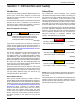
Troubleshooting Section 5: Troubleshooting Troubleshooting the Lights DANGER Electrocution. Potentially lethal voltages are present in this equipment. Render the equipment safe before attempting repairs or maintenance. Failure to do so will result in death or serious injury. IMPORTANT NOTE: Only a qualified electrician should troubleshoot or repair electrical problems occurring in this equipment.
Troubleshooting This page intentionally left blank.
4 2 Owner’s Manual for PLT240 Light Tower TB A2 TB A1 12 LIGHT #2 12 OR 5A 12 BK LIGHT #1 RD 12 BN BK DRIVER 2 12 BL 12 N N 12 BK 5A 12 TB A4 N 12 TB A3 N 12 BL BL 12 BL 12 BL 120V/20A 5-20R BK 12 LIGHT #3 NEUTRAL ISOLATED BL NEUTRAL BAR BK GFCI 12 BK 12 5A L1 TB B1 BK GND RD 12 120V/20A Edison Inlet BK/WT 20A 14 L4 LIGHT #4 L2 BK 12 14 12 BN BK DRIVER 2 12 BL 14 12 TB B2 YL NEUTRAL 14 TB B3 12 N WT BK/BL TB B4 GN/YL 12 12 BN BK DRIVER 3 12 BL 14 12 2-POL
Wiring Diagrams This page intentionally left blank.
Part No. 54800 Rev. A 09/15/16 ©2016 Generac Mobile Products LLC. All rights reserved Specifications are subject to change without notice. No reproduction allowed in any form without prior written consent from Generac Mobile Products LLC. Generac Mobile Products 215 Power Drive, Berlin, WI 54923 GeneracMobileProducts.