
Product Manual

General Information
6 Automatic Transfer Switch Owner’s Manual
Utility Service Circuit Breaker (if equipped)
The utility service and generator disconnect circuit break-
ers for 100 amp models are:
• Type BQ, 2-pole
• 10,000 A/C
• 120/240VAC, 100A
• 50/60 Hertz
• Wire range: #1 - #8 AWG (Cu/Al)
• The conductor tightening torque is 50 in-lbs. (5.6
Nm).
The utility service circuit breakers for 150/200 amp
models are:
• Type 225AF, 2-pole
• 22,000 A/C
• 120/240VAC, 150A/200A
• 50/60 Hertz
• Wire range:
– Line: 300 MCM - 6 STR (Cu/Al)
– Load - ATS: 250 MCM - 6 STR (Cu/Al)
• The conductor tightening torque is:
– Line: 375 in-lbs (42.4 Nm)
– Load - ATS: 275 in-lbs. (31 Nm)
The utility service circuit breakers for Siemens 150/200
amp models are:
• Siemens, Type QN, 2-pole
• 10,000 A/C
• 120/240VAC, 150A/200A
• 50/60 Hertz
• Wire range:
– Line: 300 MCM - 1 STR (Cu/Al)
– Load - ATS: 250 MCM - 6 STR (Cu/Al)
• The conductor tightening torque is:
– Line: 250 in-lbs (28.2 Nm)
– Load - ATS: 275 in-lbs. (31 Nm)
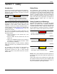
Transfer Switch Data Decal
A data decal is permanently affixed to the transfer switch
enclosure. Use this transfer switch only with the specific
limits shown on the data decal and on other decals and
labels that may be affixed to the switch. This will prevent
damage to equipment and property.
When requesting information or ordering parts for this
equipment, make sure to include all information from the
data decal.
For future reference, record the Model and Serial
numbers in the space provided on the front cover of this
manual.
Transfer Switch Enclosure
The standard switch enclosure is a National Electrical
Manufacturer’s Association (NEMA) and UL 3R type. UL
and NEMA 3R (indoor/outdoor rated) type enclosures
primarily provide a degree of protection against falling
rain and sleet; are undamaged by the formation of ice on
the enclosure.
Safe Use of Transfer Switch
Before installing, operating or servicing this equipment,
read the Safety Rules carefully. Comply strictly with all
Safety Rules to prevent accidents and/or damage to the
equipment. The manufacturer recommends that a copy
of the Safety Rules be posted near the transfer switch.
Also, be sure to read all instructions and information
found on tags, labels and decals affixed to the
equipment.
Two publications that outline the safe use of transfer
switches are the following:
• NFPA 70; National Electrical Code
• UL 1008: Standard for Safety—Automatic Transfer
Switches
NOTE: It is essential to use the latest version of any
standard to guarantee correct and current information.
Load Management Options
Load management systems are designed to work
together to prevent a generator from being overloaded by
large appliance loads. A Smart A/C Module (SACM) is
provided as standard equipment with this switch. An
optional Smart Management Module (SMM) is also
available.
Smart A/C Module (SACM)
Up to four air conditioner loads can be managed by the
SACM. The SACM manages the loads by “shedding” the
connected loads in the event of a drop in generator
frequency (overload). Loads to be “shed” are in 4 priority
levels on the module.
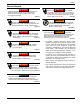
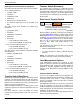
See Figure 2-2. Priorities A/C 1-4 (A) have connections
for an air conditioner. To control an air conditioner, no
additional equipment is required. Internal normally closed
relays interrupt the 24 VAC thermostat control signal to
disable the air conditioner load.
Four LEDs, located on the SACM (B), illuminate when a
load is connected and powered.
(000100a)
WARNING
Consult Manual. Read and understand manual
completely before using product. Failure to
completely understand manual and product
could result in death or serious injury.