
Product Manual

General Information
Automatic Transfer Switch Owner’s Manual 5
Section 2: General Information
Unpacking
Carefully unpack the transfer switch. Inspect closely for
any damage that might have occurred during shipment.
The purchaser must file with the carrier any claims for
loss or damage incurred while in transit.
Check that all packing material is completely removed
from the switch prior to installation.
Equipment Description
This automatic transfer switch is used for transferring
electrical load from a utility (normal) power source to a
generator (standby) power source. Transfer of electrical
loads occurs automatically when the utility power source
has failed or is substantially reduced and the generator
source voltage and frequency have reached an
acceptable level. The transfer switch prevents electrical
feedback between two different power sources (such as
the utility and generator sources) and, for that reason,
codes require it in all standby electric system installations.
The transfer switch consists of a transfer mechanism,
utility service disconnect circuit breaker (if equipped), and
a Smart A/C module incorporating fuses and two terminal
blocks for transfer switch connections.
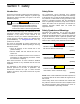
Transfer Switch Mechanism
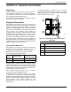
See Figure 2-1. This switch is used with a single-phase
system when the single-phase neutral line is to be
connected to a neutral lug and is not to be switched.
Solderless, screw-type terminal lugs are standard.
The conductor size range is as follows:
This transfer switch is suitable for control of motors, electric
discharge lamps, tungsten filament and electric heating
equipment where the sum of motor full load ampere ratings
and the ampere ratings of other loads do not exceed the
ampere rating of the switch and the tungsten load does not
exceed 30 percent of the switch rating.
This UL listed transfer switch is for use in optional
standby systems only (NEC article 702).
A 100A rated switch is suitable for use on circuits capable
of delivering not more than 10,000 RMS symmetrical
amperes, 250 VAC maximum, when protected by a 100A
maximum circuit breaker (Siemens types QP or BQ) or
150A maximum circuit breaker (Square D Q2,
Westinghouse CA-CAH, General Electric TQ2 and
Siemens QJ2).
A 200A rated switch is suitable for use on a circuit
capable of 22,000 RMS symmetrical amperes, 240 VAC
when protected by a circuit breaker without an adjustable
short time response or by fuses.
Figure 2-1. Typical Single-Phase ATS Transfer
Mechanism
Switch
Rating
Wire Range
Conductor
Tightening Torque
100A #14-1/0 AWG (Cu/Al) 50 in-lbs (5.6 Nm)
150/200A #6-250 MCM (Cu/Al) 275 in-lbs (31 Nm)
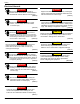
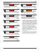
A Utility Closing Coil
B Generator Closing Coil
C Utility Lugs (N1 & N2)
D Generator Lugs (E1 & E2)
E Load Lugs (T1 & T2)
000219
A
B
C
D
E