Owner’s Manual For Automatic Transfer Switch 100 - 200 Amp, Service Entrance / Non-Service Entrance Model Number RXSW100A3 RXSC100A3 RXSW150A3 RXSW200A3 RXSC200A3 SERIAL NUMBER: _________________________ DATE PURCHASED:________________________ WWW.GENERAC.COM 888-436-3722 Para español , visita: http://www.generac.com/service-support/product-support-lookup Pour le français, visiter : http://www.generac.
WARNING California Proposition 65. Engine exhaust and some of its constituents are known to the state of California to cause cancer, birth defects, and other reproductive harm. (000004) WARNING California Proposition 65. This product contains or emits chemicals known to the state of California to cause cancer, birth defects, and other reproductive harm.
Table of Contents Section 1: Safety Introduction ..........................................................1 Safety Rules .........................................................1 Safety Symbols and Meanings ...........................1 Electrical Hazards ................................................2 General Hazards ..................................................3 Section 2: General Information Unpacking ............................................................5 Equipment Description ...........
This page intentionally left blank.
Safety Section 1: Safety Introduction Safety Rules Thank you for purchasing a Generac Power Systems Inc. product. This unit has been designed to provide high performance, efficient operation, and years of use when maintained properly. The manufacturer cannot anticipate every possible circumstance that might involve a hazard. The warnings in this manual, and on tags and decals affixed to the unit are, therefore, not all inclusive.
Safety Electrical Hazards DANGER DANGER Electrocution. High voltage is present at transfer switch and terminals. Contact with live terminals will result in death or serious injury. (000129) DANGER Equipment malfunction. Installing a dirty or damaged transfer switch will cause equipment malfunction and will result in death or serious injury. (000119) WARNING Electrocution. Water contact with a power source, if not avoided, will result in death or serious injury.
Safety General Hazards DANGER DANGER Electrical backfeed. Use only approved switchgear to isolate generator from the normal power source. Failure to do so will result in death, serious injury, and equipment damage. (000237) DANGER Electrocution. In the event of electrical accident, immediately shut power OFF. Use non-conductive implements to free victim from live conductor. Apply first aid and get medical help. Failure to do so will result in death or serious injury. (000145) WARNING Electrocution.
Safety This page intentionally left blank.
General Information Section 2: General Information Unpacking Carefully unpack the transfer switch. Inspect closely for any damage that might have occurred during shipment. The purchaser must file with the carrier any claims for loss or damage incurred while in transit. Check that all packing material is completely removed from the switch prior to installation.
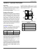
General Information Utility Service Circuit Breaker (if equipped) Transfer Switch Enclosure The utility service and generator disconnect circuit breakers for 100 amp models are: The standard switch enclosure is a National Electrical Manufacturer’s Association (NEMA) and UL 3R type. UL and NEMA 3R (indoor/outdoor rated) type enclosures primarily provide a degree of protection against falling rain and sleet; are undamaged by the formation of ice on the enclosure.
General Information See Figure 2-2. The SACM has a test button (C) used to simulate an overload condition. This button operates even when the transfer signal is inactive. The Generator Control Wiring is connected to terminals (D). C B Application Considerations Generator overload condition is determined by generator frequency. Loads are shed when frequency is less than 58 Hz for three seconds or less than 50 Hz for ½ second (for 60 Hz systems).
General Information This page intentionally left blank.
Installation Section 3: Installation Introduction to Installation This equipment has been wired and tested at the factory. Installing the switch includes the following procedures: • • • • • Mounting the enclosure. Install the transfer switch as close as possible to the electrical loads that are to be connected to it. Mount the switch vertically to a rigid supporting structure. To prevent switch distortion, level all mounting points. If necessary, use washers behind mounting holes to level the unit.
Installation Connecting Power Source and Generator Power Supply DANGER Electrocution. Turn utility and emergency power supplies to OFF before connecting power source and load lines. Failure to do so will result in death or serious injury. (000116) For transfer switches installed in wet locations, power cables or conduits entering above the level of uninsulated live parts shall use fittings listed for use in wet locations as required by 312.2 in the NEC.
Installation Connecting Start Circuit Wires Control system interconnections consist of N1, N2, and T1, and leads 23, 0, and 194 (see Figure 3-3). The generator control wiring is a Class 1 signaling circuit. Reference instruction manual of specific engine generator for wiring connection details. Screw heads are straight bladed and cross-bladed, and should be tightened to 3.5 in-lb (0.4 Nm).
Installation A Thermostat 1 A B Air Conditioner 1 B C Thermostat 2 1 C 2 1 2 1 2 1 2 D D Air Conditioner 2 E Thermostat 3 F Air Conditioner 3 T1 N1 E 0 N1 F N2 G G Thermostat 4 N2 T1 H Air Conditioner 4 194 0 GROUND 194 +12V T1 (fused) Battery Charge 23 23 TRANSFER Replace with Littlefuse® 021606.3MXHP, Optifuse® FCD-6.3A or Generac 10000005117 250 vac, 6.
Installation Auxiliary Contact Fault Current Label See Figure 3-4. If desired, there is one normally-closed Auxiliary Contact (A) on the transfer switch to operate customer accessories, remote advisory lights, or remote annunciator devices. A suitable power source must be connected to the common terminal. If needed, an extra auxiliary contact can be added. See Figure 3-5.
Installation 14 Automatic Transfer Switch Owner’s Manual
Operation Section 4: Operation Functional Tests and Adjustments Following transfer switch installation and interconnection, inspect the entire installation carefully. A competent, qualified electrician should inspect it. The installation should comply strictly with all applicable codes, standards, and regulations. When absolutely certain the installation is proper and correct, complete a functional test of the system. CAUTION Equipment damage.
Operation Close to Generator Source Side Before proceeding, verify the position of the switch by observing the position of the manual operation handle in Figure 4-1. If the handle is DOWN, the contacts are closed in the generator (standby) position. No further action is required. If the handle is UP, proceed with Step 1. 1. With the handle inserted into the movable contact carrier arm, move the handle DOWN. Be sure to hold on to the handle as it will move quickly after the center of travel. 2.
Operation 5. Set the generator main circuit breaker to ON or CLOSED. The generator now powers all LOAD circuits. Check generator operation under load as follows: • Turn on electrical loads to the full rated wattage/amperage capacity of the generator. DO NOT OVERLOAD. • With maximum rated load applied, check voltage and frequency across transfer switch terminals E1 and E2. Voltage should be greater than 230 VAC (240 VAC system); frequency should be greater than 59 Hz.
Operation Shutting Generator Down To Perform Maintenance 1. Turn the main utility disconnect OFF (OPEN). SACM Fuse Service See Figure 4-2. A fuse removal and installation tool (A) is included in the SACM housing. 2. Turn the MLCB (generator disconnect) on the generator to OFF (OPEN). 3. Press the OFF mode button on the controller and follow maintenance procedure(s). To turn the generator back ON: 1. Put the generator into AUTO mode. 2. Set the MLCB (generator disconnect) on the generator to ON (CLOSED).
Drawings and Diagrams Section 5: Drawings and Diagrams Installation Drawings No.
Drawings and Diagrams No.
Drawings and Diagrams Interconnection Drawings No.
Drawings and Diagrams No.
Drawings and Diagrams No.
Drawings and Diagrams No.
Drawings and Diagrams This page intentionally left blank.
Drawings and Diagrams 26 Automatic Transfer Switch Owner’s Manual
Part No. 10000009569 Rev A 02/21/17 ©2017 Generac Power Systems, Inc. All rights reserved Specifications are subject to change without notice. No reproduction allowed in any form without prior written consent from Generac Power Systems, Inc. Generac Power Systems, Inc. S45 W29290 Hwy. 59 Waukesha, WI 53189 1-888-GENERAC (1-888-436-3722) www.generac.