Owner’s Manual For Automatic Transfer Switch 200 Amp, Single Phase, 240 VAC, Service Rated, 8–16 Circuit Load Center Model Number RTSW200A3F 003722 SERIAL NUMBER: _________________________ DATE PURCHASED:________________________ WWW.GENERAC.COM 888-436-3722 Para español , visita: http://www.generac.com/service-support/product-support-lookup Pour le français, visiter : http://www.generac.
WARNING California Proposition 65. Engine exhaust and some of its constituents are known to the state of California to cause cancer, birth defects, and other reproductive harm. (000004) WARNING California Proposition 65. This product contains or emits chemicals known to the state of California to cause cancer, birth defects, and other reproductive harm.
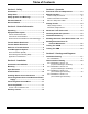
Table of Contents Section 1: Safety Section 4: Operation Introduction ..........................................................1 Functional Tests and Adjustments .................. 13 Safety Rules .........................................................1 Manual Operation .............................................. 13 Safety Symbols and Meanings ...........................1 Close to Utility Source Side .......................................13 Electrical Hazards .................................
This page intentionally left blank.
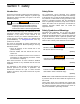
Safety Section 1: Safety Introduction Safety Rules Thank you for purchasing a Generac Power Systems Inc. product. This unit has been designed to provide high performance, efficient operation, and years of use when maintained properly. The manufacturer cannot anticipate every possible circumstance that might involve a hazard. The warnings in this manual, and on tags and decals affixed to the unit are, therefore, not all inclusive.
Safety Electrical Hazards DANGER DANGER Electrocution. High voltage is present at transfer switch and terminals. Contact with live terminals will result in death or serious injury. (000129) DANGER Equipment malfunction. Installing a dirty or damaged transfer switch will cause equipment malfunction and will result in death or serious injury. (000119) WARNING Electrocution. Water contact with a power source, if not avoided, will result in death or serious injury.
Safety General Hazards DANGER DANGER Electrical backfeed. Use only approved switchgear to isolate generator from the normal power source. Failure to do so will result in death, serious injury, and equipment damage. (000237) DANGER Electrocution. High voltage is present at transfer switch and terminals. Contact with live terminals will result in death or serious injury. (000129) DANGER Electrocution. Turn utility supply OFF before working on utility connections of the transfer switch.
Safety This page intentionally left blank.
General Information Section 2: General Information Unpacking C Carefully unpack the transfer switch. Inspect closely for any damage that might have occurred during shipment. The purchaser must file with the carrier any claims for loss or damage incurred while in transit. Check that all packing material is completely removed from the switch prior to installation.
General Information Load Center Circuit Breakers Transfer Switch Enclosure This switch is listed for use with the following one inch breakers: The standard switch enclosure type is a NEMA 3R and UL 3R outdoor rated enclosure. • Siemens • Murray • Eaton* • Square D Homeline* Safe Use of Transfer Switch WARNING Consult Manual. Read and understand manual completely before using product. Failure to completely understand manual and product could result in death or serious injury.
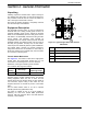
General Information Application Considerations 0 GROUND 194 +12V 23 TRANSFER T1 A NEUTRAL A/C 1 B A/C 2 A/C 1 A/C 2 Generator overload condition is determined by generator frequency. Loads are shed when frequency is less than 58 Hz for three seconds or less than 50 Hz for ½ second (for 60 Hz systems). The SACM can be used in conjunction with individual SMMs to manage a combined total of eight loads. • Use Priorities A/C 1-4 on the SACM as the top priorities, then up to four SMMs as Priorities 5-8.
General Information This page intentionally left blank.
Installation Section 3: Installation Introduction to Installation This equipment has been wired and tested at the factory. Installing the switch includes the following procedures: • • • • • Mounting the enclosure. Install the transfer switch as close as possible to the electrical loads that are to be connected to it. Mount the switch vertically to a rigid supporting structure. To prevent switch distortion, level all mounting points. If necessary, use washers behind mounting holes to level the unit.
Installation Install Breakers 1. See Figure 3-2. Insert tab on each breaker (A) into the hook on the bus (B). Push the breaker into the bus until it snaps into place. B 2. Connect utility neutral and ground to the Load Center Neutral and Ground terminals. Neutral and Ground terminals on the Load Center are bonded to each other with a jumper wire. 3. Connect loads to the Integrated Load Center with customer-supplied circuit breakers. 4. See Figure 2-1 and Figure 3-3.
Installation NOTE: A Neutral to Ground bonding screw (A) is provided for use if required by local codes. Conductor sizes must be adequate to handle the maximum current to which they will be subjected, based on the 75°C column of tables, charts, etc. used to size conductors. The installation must comply fully with all applicable codes, standards and regulations. All power cables can enter the enclosure through the provided knockouts.
Installation A Thermostat 1 A 0 GROUND B Air Conditioner 1 194 +12V B T1 23 TRANSFER 00 NEUTRAL E C Thermostat 4 F D Air Conditioner 4 A/C 1 A/C 2 A/C 1 A/C 2 E Thermostat 2 G A/C 3 F Air Conditioner 2 A/C 3 A/C 4 C A/C 4 H G Thermostat 3 D 003693 H Air Conditioner 3 Figure 3-4. Typical SACM Connections Auxiliary Contact See Figure 3-5.
Operation Section 4: Operation Functional Tests and Adjustments Following transfer switch installation and interconnection, inspect the entire installation carefully. A competent, qualified electrician should inspect it. The installation should comply strictly with all applicable codes, standards, and regulations. When absolutely certain the installation is proper and correct, complete a functional test of the system. CAUTION Equipment damage.
Operation Close to Generator Source Side Before proceeding, verify the position of the switch by observing the position of the manual operation handle in Figure 4-1. If the handle is DOWN, the contacts are closed in the generator (standby) position. No further action is required. If the handle is UP, proceed with Step 1. 1. With the handle inserted into the movable contact carrier arm, move the handle DOWN. Be sure to hold on to the handle as it will move quickly after the center of travel. 2.
Operation 5. Set the generator main circuit breaker to ON or CLOSED. The generator now powers all LOAD circuits. Check generator operation under load as follows: • Turn on electrical loads to the full rated wattage/amperage capacity of the generator. DO NOT OVERLOAD. • With maximum rated load applied, check voltage and frequency across transfer switch terminals E1 and E2. Voltage should be greater than 230 VAC (240 VAC system); frequency should be greater than 59 Hz.
Operation Shutting Generator Down To Perform Maintenance 1. Turn the main utility disconnect OFF (OPEN). Testing The SMM Refer to the SMM Owner’s/Installation Manual for testing procedure. 2. Turn the MLCB (generator disconnect) on the generator to OFF (OPEN). 3. Allow generator to cool down for one minute with no load. 4. Press the OFF mode button on the controller and follow maintenance procedure(s). To turn the generator back ON: 1. Put the generator into AUTO mode. 2.
Automatic Transfer Switch Owner’s Manual A B 1219.21 [48.000] 4 DRAWING CREATED FROM PRO/ENGINEER 3D FILE. ECO MODIFICATION TO BE APPLIED TO SOLID MODEL ONLY. 4 65.16 [2.565] 70.47 [2.774] 1090 [42.913] 3 424 [16.693] 571.5 [22.500] 3 1/1 SEE DETAIL A SH REV A A.
Drawings and Diagrams Interconnection Drawing No.
Drawings and Diagrams No.
Drawings and Diagrams No.
Drawings and Diagrams No.
Drawings and Diagrams This page intentionally left blank.
Part No. 10000007836 Rev A 11/17/2016 ©2016 Generac Power Systems, Inc. All rights reserved Specifications are subject to change without notice. No reproduction allowed in any form without prior written consent from Generac Power Systems, Inc. Generac Power Systems, Inc. S45 W29290 Hwy. 59 Waukesha, WI 53189 1-888-GENERAC (1-888-436-3722) www.generac.