Owner’s Manual for Tow-Behind Field and Brush Mower 005815 MODEL NUMBER: _________________________ SERIAL NUMBER: _________________________ DATE PURCHASED:________________________ Register your Generac product at: WWW.GENERAC.
WARNING CANCER AND REPRODUCTIVE HARM www.P65Warnings.ca.gov.
Table of Contents Section 1: Safety Rules & General Information Section 3: Operation Introduction ..................................................................1 Read This Manual Thoroughly ....................................1 Operating Parameters ...............................................13 Safety Rules .................................................................1 How to Obtain Service .................................................1 General Hazards ....................................
This page intentionally left blank.
Safety Rules & General Information Section 1: Safety Rules & General Information Introduction Thank you for purchasing a Generac Power Systems Inc. product. This unit has been designed to provide high performance, efficient operation, and years of use when maintained properly. The information in this manual is accurate based on products produced at the time of publication. The manufacturer reserves the right to make technical updates, corrections, and product revisions at any time without notice.
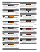
Safety Rules & General Information General Hazards WARNING WARNING Accidental Start-up. Disconnect the negative battery cable, then the positive battery cable when working on unit. Failure to do so could result in death or serious injury. (000130) Risk of injury. Do not operate or service this machine if not fully alert. Fatigue can impair the ability to service this equipment and could result in death or serious injury. (000215) WARNING WARNING Personal injury. Keep out of reach of children.
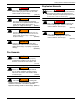
Safety Rules & General Information Explosion Hazards DANGER Risk of fire. Allow fuel spills to completely dry before starting engine. Failure to do so will result in death or serious injury. (000174) DANGER Explosion and fire. Fuel and vapors are extremely flammable and explosive. No leakage of fuel is permitted. Keep fire and spark away. Failure to do so will result in death or serious injury. (000192) WARNING Fire risk. Fuel and vapors are extremely flammable. Do not operate indoors.
Safety Rules & General Information Safety and Operating Decals This unit features numerous safety and operating decals. These decals provide important operating instructions and warn of dangers and hazards. Replace damaged or missing safety and operating decals immediately.
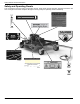
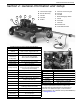
General Information and Setup Section 2: General Information and Setup C A D E F G B A Hand Crank Height F Generac G-Force Engine B Electric Start Key G Fuel Fill C Throttle H Tow Bar D Oil Filter I Blade Disengage Switch E Muffler J K L M N Oil Fill Fuel Filter Oil Drain Fuel Shut-Off Chain Debris Guard H I N Tow-Behind Field and Brush Mower Specifications Battery 9 Ah Wheels Front: 11 X 4-5, Flat Free Rear: 13 x 5-6, Lugged with Tube Tether Length 14.42 ft (4.
General Information and Setup Emissions The United States Environmental Protection Agency (US EPA) (and California Air Resources Board (CARB), for engines/equipment certified to California standards) requires that this engine/equipment complies with exhaust and evaporative emissions standards. Locate the emissions compliance decal on the engine to determine applicable standards. For emissions warranty information, please reference the included emissions warranty.
General Information and Setup Installing Hitch 7. Install clevis pin and hair pin with washer (M). 1. See Figure 2-4. Attach chain connector (A) to the end of each safety chain (B) with the shorter side (C) toward the safety chain. Tighten with 10 mm wrench. A B C 006210 Figure 2-4. Chain Connector WARNING Personal injury. Install clevis pins from the bottom with the washers and hair pins on top. Failure to do so could result in death, serious injury, equipment or property damage.
General Information and Setup Maintenance Meter Installation Adding Oil 1. See Figure 2-9. Align slot in mounting bracket (A) with mounting hole in control board, and secure mounting bracket to control board with 5/16-18 x 1” bolt and 5/16” locknut (B). 2. Insert meter (C) into the bracket opening. Press the meter firmly to ensure the retaining clips on the sides of the meter have snapped into place. A CAUTION Engine damage. Verify proper type and quantity of engine oil prior to starting engine.
General Information and Setup Adding Fuel DANGER Explosion and Fire. Fuel and vapors are extremely flammable and explosive. Add fuel in a well ventilated area. Keep fire and spark away. Failure to do so will result in death or serious injury. (000105) Kits can be obtained by contacting Generac Customer Service at 1-888-436-3722 (1-888-GENERAC), or www.generac.com. Kits must be installed by a qualified individual.
General Information and Setup Hitching Unit to Tow Vehicle 5. Cross safety chains under ball hitch by attaching left chain to right anchor and right chain to left anchor. WARNING Loss of control. Verify the unit is securely attached to the tow vehicle. Failure to securely attach the unit could result in loss of control, resulting in death, serious injury, unit, or property damage. (000506) WARNING Loss of control. Do not tow unit with a passenger car or truck.
General Information and Setup UTV Extension Blade Clutch Burnishing The blade clutch must be burnished before initial use to ensure optimum engaging and braking action. WARNING Accidental start-up. Before servicing or detangling, shut down unit, allow to cool, remove keys, and disconnect spark plug wire(s). Failure to do so could result in death, serious injury, or equipment damage. (000415) 1. See Figure 2-19. Pull existing wire harness connector (A) from blade engage control box (B).
General Information and Setup This page intentionally left blank.
Operation Section 3: Operation WARNING Consult Manual. Read and understand manual completely before using product. Failure to completely understand manual and product could result in death or serious injury. (000100a) WARNING Hot Surfaces. When operating machine, do not touch hot surfaces. Keep machine away from combustibles during use. Hot surfaces could result in severe burns or fire. (000108) WARNING Personal injury. This unit is designed for cutting grass and brush.
Operation Before Starting Engine Starting Engine 1. Verify blade switch safety cover is closed. WARNING Projectile risk. Remove all debris from work area before operating unit. Failure to do so could result in death, serious injury, or property or equipment damage. (000410) 2. See Figure 3-4. Move throttle (A) to CHOKE position. B WARNING Projectile risk. Be aware of surroundings at all times when operating unit. Disengage mower blades if people or animals enter the work space.
Operation Adjusting Mower Deck Height 4. WARNING Personal injury. Shut engine OFF and keep hands and feet away while adjusting deck height. Failure to do so could result in death or serious injury. (000458) See Figure 3-8. Rotate both height adjusters in the same direction, switching sides every ten full turns until the top of sway brace (C) aligns with the desired cutting height lines on height adjust label (D). WARNING Personal injury.
Operation 4. See Figure 3-10. Remove clevis pin and hair pin with washer (F) securing tow bar extension. 2. See Figure 3-13. Remove remote control cable (A) from cable clamps (B). H A G F B 005921 Figure 3-10. Offsetting the Tow Bar Extension 5. Rotate tow bar extension from no offset to medium offset (G) or full offset (H). IMPORTANT NOTE: See Figure 3-11. Tow bar offset angle (I) and tow bar extension offset angle (J) must match to ensure proper tracking. 005872 Figure 3-13.
Operation Mowing Slopes and Uneven Terrain WARNING Personal injury. Never operate mower on wet or slippery slopes as loss of control may result. Operating on wet or slippery slopes could result in death, serious injury, or property or equipment damage. (000413) WARNING Personal injury. When towing on slopes, verify towing vehicle has sufficient power and weight. Failure to adhere to these practices could result in death, serious injury, unit, or property damage. (000453) WARNING Loss of control.
Operation This page intentionally left blank.
Maintenance and Troubleshooting Section 4: Maintenance and Troubleshooting Maintenance Regular maintenance will improve performance and extend engine/equipment life. Regular maintenance, replacement, or repair of the emissions control devices and systems may be performed by any repair shop or person of the owner’s choosing. To obtain emissions control warranty service free of charge, contact Generac Customer Service at 1-888436-3722 (1-888-GENERAC), or www.generac.com. See the emissions warranty.
Maintenance and Troubleshooting Operating Maintenance Meter See Figure 4-1. The maintenance meter monitors accumulated running time, time until engine oil needs to be changed, and time until lubrication is recommended. Pressing function button (A) cycles through the meter functions. 2. Remove drain plug with an 8 mm Allen wrench and allow oil to drain into the container. 3. See Figure 4-3. Remove oil filter (E) with an oil filter wrench. A E Figure 4-1.
Maintenance and Troubleshooting Servicing Spark Plug Height Adjuster Thread Lubrication 1. Raise deck to the highest position. To service spark plug: 2. See Figure 4-7. Clean height adjuster threads (C) using a wire brush or rag. 1. Clean area around spark plug. 2. Remove and inspect spark plug. 3. See Figure 4-4. Inspect electrode gap with wire feel gauge and reset spark plug gap to 024-.032 in (0.6-0.8 mm). C 005937 Figure 4-7. Height Adjuster Threads 000211 Figure 4-4. Spark Plug 4.
Maintenance and Troubleshooting 5. See Figure 4-10. Lift gas tank plate (H) and position gas tank plate on fuel line side of the machine. NOTE: When lifting the gas tank plate do not stress the fuel or vapor lines. Installing Drive Belt 1. Insert new drive belt under the clutch. 2. Pull idler pulley out and position drive belt onto the clutch. 3. Place drive belt over the top of the blade pulley. H 4. Insert the “V” of drive belt into blade pulley groove on the left side of the machine.
Maintenance and Troubleshooting Replacing Carbon Canister Ball Hitch Receiver Adjustment 1. Remove the gas tank plate. See Removing and Replacing Drive Belt 1. See Figure 4-14. Cut cable ties (A) securing carbon canister and purge hose. Ball Hitch Receiver Adjustment Check 1. See Figure 4-15. Place 2" ball in receiver socket and close latch assembly. Verify locking trigger is properly engaged in detent. B A A 005946 Figure 4-14. Carbon Canister 2.
Maintenance and Troubleshooting Battery Care Proper care can extend the life of a battery. For best battery performance and long battery life. WARNING Explosion. Batteries emit explosive gases while charging. Keep fire and spark away. Wear protective gear when working with batteries. Failure to do so could result in death or serious injury. (000137a) being used. Operate the engine for at least 45 minutes to maintain proper charge. • Do not charge a fully charged battery.
Maintenance and Troubleshooting Troubleshooting Symptom Possible Cause Verify fuel shut-off valve is OPEN. Verify blade switch safety cover is in DISENGAGED position. Verify spark plug wire is attached. See Starting Engine. Verify throttle is in CHOKE position if engine is cold. Fuel may be old. Change as necessary. Engine will not start. Spark plug may be dirty or cracked. Change as necessary.
Maintenance and Troubleshooting Symptom Possible Cause Pulley groove dirty or damaged. Clean pulley with steel wool. File off cuts or nicks. Belt frays or rolls over pulley Inspect belt for wear or hard spots. Inspect belt for stretching. Tighten blade carrier mounting bolt as tight with at least a 1 ft long 1-1/8” wrench. Excessive vibration when engaging the mower blade Tighten swinging blade mounting hardware. See Replacing Swinging Blades Replace swinging blade if chipped, bent, or broken.
Part No. 10000024620 Rev. A 04/30/2018 ©2018 Generac Power Systems, Inc. All rights reserved Specifications are subject to change without notice. No reproduction allowed in any form without prior written consent from Generac Power Systems, Inc. Generac Power Systems, Inc. S45 W29290 Hwy. 59 Waukesha, WI 53189 1-888-GENERAC (1-888-436-3722) www.generac.