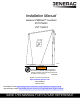
Installation Manual Generac PWRcell™ Inverters XVT076A03 XVT114G03 009954 WARNING Loss of life. This product is not intended to be used in a critical life support application. Failure to adhere to this warning could result in death or serious injury. (000209b) Register your Generac product at: https://pwrfleet.generac.com 1-888-GENERAC Register (888-436-3722) your Generac product at: WWW.GENERAC.COM Para español, visita: http://www.generac.
Use this page to record important information about your Generac Product Record the information found on your unit data label on this page. See Serial Number Location. When contacting an Independent Authorized Service Dealer (IASD) or Generac Customer Service, always supply the complete model number and serial number of the unit. Table 1: PWRcell Inverter Important Information Unit Model Number Unit Serial Number Date Purchased Commissioning Date WARNING CANCER AND REPRODUCTIVE HARM www.P65Warnings.ca.
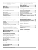
Section 1: Safety Rules & General Information Section 6: Commissioning and Setup Introduction ..........................................................1 General Information .......................................... 25 Safety Rules .........................................................1 General Hazards ..................................................2 Electrical Hazards ................................................3 Section 2: General Information Specifications ................................
This page intentionally left blank.
Safety Rules & General Information Section 1: Safety Rules & General Information Introduction Thank you for purchasing a Generac PWRcell™ product. The Generac PWRcell inverter is a storage-ready inverter that connects to the PV Link™ optimizers and PWRcell batteries to form the Generac PWRcell system. This manual provides instructions for installing the PWRcell inverter, including mounting, wiring, and battery integration information.
Safety Rules & General Information General Hazards CAUTION DANGER Electrocution. Do not wear jewelry while working on this equipment. Doing so will result in death or serious injury. (000188) Equipment damage. Connect only to REbus-compatible devices to the DC bus. Never connect to any other DC power source. Connecting to other DC power sources could result in equipment damage. (000598a) • Connecting the PWRcell inverter to the electric util- DANGER Automatic start-up.
Safety Rules & General Information Electrical Hazards DANGER Electrocution. Water contact with a power source, if not avoided, will result in death or serious injury. (000104) DANGER Electrocution. PWRcell Battery front cover should be removed by a qualified technician only. Removing the front cover could result in death, serious injury, equipment or property damage. (000604) DANGER Electrocution. In the event of electrical accident, immediately shut power OFF.
Safety Rules & General Information This page intentionally left blank.
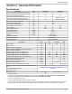
General Information Section 2: General Information Specifications Description Max. cont. grid-tied AC power @ 122°F (50ºC) Max. cont. islanded AC power @ 104°F (40°C) with single 6 module battery cabinet1 Max. cont. islanded AC power @ 104°F (40°C) with 2 battery cabinets (8 modules minimum) Max. cont.
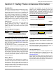
General Information Serial Number Location Component Locations Refer to Figure 2-2 to locate unit serial number (D). Record the information from this tag in Table 1: PWRcell Inverter Important Information on the inside front cover of this manual. A C Unit Dimensions D A B 009654 Figure 2-2. Component Locations B C 009955 Figure 2-1.
General Information . C F E G A D B B H D B 009893 Figure 2-3. Generac PWRcell System Example A Solar Panels B PV Link C PWRcell Battery D E F G H REbus PWRcell Inverter Grid Inverter Control Panel Loads Protected Loads REbus Status LED REbus Status LED (C) communicates REbus nanogrid status through LED color. A • Green – all devices are functioning normally and are generating power on REbus. C D • Yellow – no PV Links are generating power from PV on Rebus.
General Information Internet LED Internet LED (G) is illuminated when the inverter is connected to a router and has an IP address. A blue Internet LED does not mean that the inverter has a connection to the Generac server. Shutdown Mode DANGER Electrocution. Initiate a system-wide shutdown and turn the PWRcell DC Disconnect Switch OFF on all connected batteries before performing service. Failure to do so will result in death, serious injury, or equipment and property damage.
Location and Compliance Section 3: Location and Compliance Location Note on DC Wiring and the NEC When installing the PWRcell inverter, consider the following: • The unit can be installed in indoor or outdoor locations. • The inverter installation location must meet the working space requirements in NEC Article 110.26. Some electricians or installers may be unfamiliar with DC wiring in a residential setting. Note the following: • NEC 690.31 for DC PV circuits in buildings • NEC 215.
Location and Compliance Voltage and Frequency Trip Thresholds This unit or system is provided with fixed trip limits and shall not be aggregated above 30 kW on a single point of common connection. All PWRcell inverters are shipped from the factory in compliance with all UL1741 requirements, including IEEE1547. If permission to operate (PTO) is dependent on compliance to a specific utility standard, follow the steps covered in Installer Configuration Tool section in this manual.
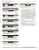
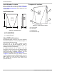
Installing PWRcell Inverter Section 4: Installing PWRcell Inverter PWRcell Inverter Dimensions and Mounting Clearances 4 in (10.16 cm) 8 in (20.32 cm) 19-1/4 in (48.9 cm) 20 in (50.8 cm) 8-1/2 in (21.6 cm) 8 in (20.32 cm ) 24-1/2 in (62.23 cm) 28-1/2 in (72.4 cm) 8 in (20.32 cm) 36 in (91.44 cm) 28 in (71.15 cm) 010508 Figure 4-1. PWRcell Inverter Dimensions and Mounting Clearances Mounting Bracket Dimensions 1-1/2 in (3.81 cm) 2-3/8 in (6.03 cm) 16 in (40.64 cm) 009990 Figure 4-2.
Installing PWRcell Inverter Mounting the Inverter CAUTION NOTE: Figure 4-3 is for illustration purposes only. Equipment damage. Mount inverter to a strong, stable surface. Never mount to drywall, plaster, or other non-structural wall treatments. Failure to mount inverter to a strong, stable surface could result in equipment or property damage. (000641a) B 1.
Electrical Connections Section 5: Electrical Connections PWRcell Inverter Wiring Compartment A H D E F G C B J I N M K L 011235 Figure 5-1.
Electrical Connections Accessing Wiring Compartment • Install reducing washers to accommodate smaller conduit sizes. • Install rain-tight DANGER Electrocution. Initiate a system-wide shutdown and turn the PWRcell DC Disconnect Switch OFF on all connected batteries before performing service. Failure to do so will result in death, serious injury, or equipment and property damage. (000600) DANGER Electrocution. Verify all system voltages are safe before wiring.
Electrical Connections 1-19/32 in 40 mm 21-23/32 in 552 mm 3-13/16 in 97 mm 2-7/32 in 1-31/32 in 56 mm 50 mm 1-21/32 in 42 mm 5-17/32 in 140 mm 5-13/32 in 137 mm 2-9/32 in 58 mm 2-5/32 in 55 mm 2-5/32 in 55 mm 1-31/32 in 50 mm 13/32 in 10 mm 2-13/16 in 72 mm 2-5/32 in 55 mm 1-3/8 in 35 mm 2-7/16 in 62 mm 1-3/4 in 45 mm 1-3/32 in 28 mm 1 in 26 mm 1-31/32 in 50 mm 1-7/8 in 48 mm 2-5/32 in 55 mm 011234 Figure 5-3. Knockout Locations Wiring Guidelines DANGER Electrocution.
Electrical Connections Table 5-4. Terminal Torques Wiring Terminal Torque AC terminals 13.3 to 15.9 in-lb (1.5 to 1.8 Nm) DC terminals 12 in-lb (1.35 Nm) Ground terminals 4 to 6 AWG: 45 in-lb (5 Nm) 8 AWG: 40 in-lb (4.5 Nm) 10 to 14 AWG: 35 in-lb (4 Nm) STOP terminals 1.9 to 2.2 in-lb (0.22 to 0.25 Nm) Grounding Bar Wiring CAUTION Equipment damage. Never connect REbus conductors to ground. Connecting REbus conductors to ground could result in equipment or property damage.
Electrical Connections DC Wiring Table 5-6. DC Wiring Terminal Specifications DANGER Electrocution. Never touch terminals when inverter and PWRcell DC disconnects are ON. Doing so will result in death or serious injury. (000686a) WARNING Equipment damage. Obey polarity markings when connecting REbus devices. Reverse-polarizing DC circuits could result in equipment or property damage. (000646) WARNING Equipment damage. Do not connect raw, unregulated battery output to inverter.
Electrical Connections Protected Load CAUTION Equipment damage. Never connect protected loads terminals to other sources of power, including any other inverter, the utility grid, or a generator. Doing so could result in equipment or property damage. (000648a) CAUTION protected loads terminals. This includes when the inverter is disabled.
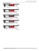
Electrical Connections NOTE: See Figure 5-6. On systems that do not include battery storage but battery storage is expected in the future, install a protected loads panel during inverter installation. The protected loads panel will be fed by the grid while the system operates in Grid Tie mode. G A B C E A B C D E G PV Array PWRcell Inverter Protected Loads Panel Protected Loads Disconnect AC Main Panel Utility D 009998 Figure 5-6.
Electrical Connections Connecting Ethernet IMPORTANT NOTE: Generac requires all PWRcell system components to be connected to the Internet and to maintain such connection throughout the warranty period. Internet connectivity is established via the PWRcell inverter. By installing the PWRcell inverter and connecting it to the Internet, Customer agrees that Generac may remotely monitor the use and condition of the system and update the system's software and firmware, as necessary, without further notice.
Electrical Connections Connecting CTs to the Inverter • CT input jack is a double-stacked RJ-45 jack. • Either the top or bottom port may be used. • Both jacks may be used when multiple sets of CTs are required. 1. See Figure 5-8. Connect CT leads to RJ-45 Breakout Adapter’s (M) push terminals according to the label on the breakout adapter. ATS : CTs NOTE: Use yellow lead for CTx+ and use green lead for CTx-. I H L K J 010001 Figure 5-9.
Electrical Connections Connecting CTs to Multiple PWRcell Systems/ Inverters When an installation has multiple PWRcell inverter systems, either: • Run a set of CTs for each inverter. • Run a set of CTs to one inverter and then run a Cat 5 cable from the spare CT port within that inverter to any CT port within another inverter. When running separate sets of CTs for each inverter, the load value displayed on each inverter screen will be the total load measured by the CTs.
Electrical Connections Table 5-10. CT Setpoints Setpoint CalOverride Behavior • Overrides CT calibration. • When set to OFF, the inverter detects the CTs number and direction of Default Units OFF N/A 1,500 Turns CTs. • A value of ON assumes a specific orientation and direction of CTs. CTTurnsRatio • Turns ratio of the CTs installed.
Electrical Connections Other Accessories Revenue Grade Meter (RGM) Kit A Generac PWRview Meter is an optional accessory for the PWRcell Inverter and may be factory or field installed. When installed at the bottom of the wiring cabinet, it also uses additional CTs that are provided. Complete installation instructions are included with the RGM kit. Order part number: PCRGM1.
Commissioning and Setup Section 6: Commissioning and Setup System Configuration The PWRcell system is a flexible, highly customizable system that can be configured in a number of ways to meet customer need. Correct system configuration requires selecting the right equipment and the correct system mode for the system. See the Generac PWRcell Inverter Owner’s Manual for information on system modes and other user-configurable settings.
Commissioning and Setup Connecting PWRcell Inverter to AC Power Turn ON main AC backfeed to power-up the inverter. See Figure 6-2. On power-up, the home screen will appear on the control panel LCD with the operational mode listed at the top of the home screen. 3. See Figure 6-4. Use the up and down arrows to highlight the desired mode and press the center button to select. System Mode Safety Shutdown Grid Tie * Self Supply Clean Backup < EXIT Menu SCROLL > NEXT • SELECT 009967 Figure 6-4.
Commissioning and Setup Configuring Inverter Settings Adjusting Inverter Settings Configuring Systems with PWRcell Batteries Systems with a PWRcell battery must have the EnaIslanding setpoint set to ON in order to provide backup power during a grid outage. This setpoint is accessible through the Mod. Settings menu via the inverter device page. The default value for this setting from the factory is ON. Verify the PWRcell inverter protected loads disconnect is in the ON position.
Commissioning and Setup Selecting Inverter Compliance Setting (optional) By default, all Generac PWRcell Inverters ship in compliance with UL 1741, including IEEE 1547. If the system needs to be configured to comply with a different grid interconnection standard, activate the new configuration before proceeding via the Installer Configuration Tool. See Installer Configuration Tool for more information.
Commissioning and Setup PWRcell 2P Inv Menu Enable Enable Mod. Settings Calibrate CTs Cancel Confirm RCPn: 00010003XXXX < EXIT SCROLL > NEXT • SELECT REbus Beacon TOU Scheduler disabled To enable scheduler, press center button and select “Enable”. 010109 010012 Figure 6-11. Configuring TOU Schedule (1 of 4) Figure 6-9. Enabling Inverter (3 of 4) 6. See Figure 6-10. The inverter is enabled. It will create voltage at the DC terminals and begin communicating with connected REbus devices.
Commissioning and Setup 6. Use the up and down arrows to adjust the TOU Schedule. Once the desired value is set, press the center button to exit edit mode. NOTE: See the latest Time of Use Program Guide for current TOU schedule values. The program guide is available at https://www.generac.com/resources-andtools/ce-installer-resources/clean-energy-designsupport. 7. Set the Time Zone to the desired location based on Table 2: Time Zone Codes.
Commissioning and Setup Enabling Beacon TOU Disabling Beacon TOU Once the TOU Schedule is set, the scheduler will automatically enable itself and begin running. However, if the scheduler becomes disabled for any reason, follow the instructions below to re-enable the scheduler: 1. See Figure 6-19. Navigate to the Beacon device page and press the center button to enter the device menu. The scheduler can be disabled at any time. To disable the scheduler: 1. See Figure 6-21.
Commissioning and Setup Temporarily Overriding the TOU Scheduler The scheduler can be temporarily overridden at any time without disabling it. A manual override will apply until the next regularly scheduled system mode change. To temporarily override the scheduler: 1. Navigate to the system home page. 2. Press the center button. 3. Select the desired temporary system mode. NOTE: See the Generac PWRcell Inverter Owner’s Manual for more information on system modes.
Commissioning and Setup 4. See Figure 6-27. From the IP Settings menu select Manual. MAC:00:04:a3:0b:77:fc IP: 192.168.158.37 DHCP: bound, 83285s ARP: idle DNS: done ctr btn: net settings 009981 010049 Figure 6-27. Ethernet Configuration (2 of 2) 5. Adjust any of the following: • • • • IP Subnet Mask DNS Gateway NOTE: Contact your network system administrator to connect the PWRcell inverter to a restricted network. 6.
Commissioning and Setup send commands to REbus-powered devices. In this way, a PWRcell inverter behaves like a master device. If two or more master devices are communicating on the same PLM channel, REbus devices become unable to respond properly to the intended master device and the master devices will attempt to provide control for the other, often leading to communication and reporting issues. This is referred to as cross-talk.
Commissioning and Setup 6. Proceed to next crosstalked inverter and repeat the procedure. browser URL. The installer tool will appear in the browser. Installer Configuration Tool The Installer Configuration Tool allows configuration and provisioning of Generac PWRcell systems from a smartphone or laptop. The interface allows installers to configure basic settings, set inverter compliance, generate a compliance report, and understand system performance.
Commissioning and Setup 3. See Figure 6-30. To adjust a setting, click on it, select the desired change, and click Submit. Any changes selected to be made, will not be implemented unless Submit is selected at the end. 011978 Figure 6-30. PWRcell Configuration All settings can be adjusted through the inverter’s screen with the exception of the following two settings, which can only be adjusted though the Installer Configuration Tool: • Enabled SysModes.
Commissioning and Setup Export Limiting: This option is one-time settable. To unset Export Limiting, please contact Generac PWRcell Technical Support. Please be aware that once set, certain Utilities may require the request to unset this setting come from the Utility. Changing this setting from “DISABLED” to “ENABLED” via the dropdown list will limit the inverter power export to the utility grid to the value specified for Export Limit.
Commissioning and Setup Proof of Compliance The Compliance PDF validates whether the system has been set up to conform to a utility compliance ruleset. Please double check the system is configured properly by observing the ‘In compliance with’ line in the PDF. If your utility requires proof of correct configuration, save this PDF and send it to your utility. It is recommend you keep a copy on file as well. 1. To generate a proof of compliance PDF, click on the Compliance PDF tab in the navigation menu. 2.
Maintenance Section 7: Maintenance Service DANGER Electrocution. Verify all system voltages are safe before wiring. Disconnect all AC and DC sources of power before touching terminals. Failure to ensure no dangerous voltages are present on conductors and terminals before wiring will result in death or serious injury. (000642) C B DANGER Electrocution. Initiate a system-wide shutdown and turn the PWRcell DC Disconnect Switch OFF on all connected batteries before performing service.
Maintenance Recovery From an Error State To replace a fuse: 1. Initiate an inverter shutdown. See Shutdown Mode for more information. 2. See Figure 7-1. Open all PWRcell DC Disconnects (A). Verify DC voltage reported on LCD screen has dropped to below 10VDC. 3. Disconnect all sources of AC and DC Power. 4. Remove wiring compartment cover. See Accessing Wiring Compartment. 5. See Figure 7-2. Locate DC fuse holders (B). 6. Using a multi-meter, verify all PWRcell DC and AC terminals are below 10V. 7.
Troubleshooting Section 8: Troubleshooting General Troubleshooting Some of the more common problems are listed in the table below. This information is intended to be a check or verification that simple causes can be located and fixed. It does not cover all types of problems. Procedures that require in-depth knowledge or skills should be referred to an Independent Authorized Service Dealer. Table 8-1.
Troubleshooting This page intentionally left blank.
This page intentionally left blank.
® Part No. DMAN00040 Rev. B 12/3/2020 ©2020 Generac Power Systems, Inc. All rights reserved. Specifications are subject to change without notice. No reproduction allowed in any form without prior written consent from Generac Power Systems, Inc. Generac Power Systems, Inc. S45 W29290 Hwy. 59 Waukesha, WI 53189 1-888-GENERAC (1-888-436-3722) www.generac.