
User Manual
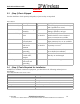
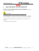
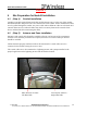
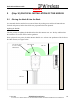
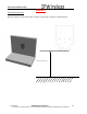
Table Of Contents
- IMPORTANT
- Legal Terms Governing This Document
- 1 OVERVIEW
- 2 PRE-INSTALLATION
- (Step 3) MOUNTING THE NODE B BRACKET
- 4 Site Preparation for Node B Installation
- 5 (Step 10) PHYSICAL INSTALLATION OF THE NODE B
- 5.1 Placing the Node B into the Rack
- 5.2 Service Area Interfaces
- 5.3 (Step 6) Grounding Installation and Inspection
- 5.4 Cable Clamp Seal
- 5.5 Connecting Power to the Node B
- Backhaul Connections to INC
- 5.7 Alarm Connections
- 5.8 Replacement of the Seal cable clamp
- 5.9 Conduit Pivot Bracket Securing
- 5.10 Closing the Door and securing the NodeB
- 5.11 GPS
- 6 (Step 11) Power up and Initial Setup of Node B
- 8
- 8 (Step 12) SOFTWARE INSTALLATION
- 9 (Step 13) On Air final check
- 10 Operation & Maintenance

Node B Installation Guide
DRAFT
17 July, 2001 IPWireless Proprietary
IT IS ILLEGAL TO MAKE COPIES OF THIS DOCUMENT WITHOUT EXPRESS PERMISSION BY IPWIRELESS
10
2.3 (Step 2) Parts Shipped
Use this checklist to check quantity and quality of parts as they are unpacked
P
ARTS
C
HECK
Part Name Description Amount Quality Checks
Node B Assembly 1 per sector Check shipping container for damage
and if quantities are correct
Bracket Assembly Node B mounting
assembly
1 per Node B Check shipping container for
damage, quantities, and type
Power Availability -48Volt or 110
VAC
1 connection
per Node B
Check to see if power cabinet is
installed and the correct amount of
power connections are available
Alarm Contacts Dry contacts for
external alarm
Check to see if external alarms for
lights, intrusion, fire, etc are available
Antenna Node B Transmit
and receive
antennas
2 antennas
per Node B
Check box for damage. Check to see
if quantity is correct.
Connectors Antenna, Power,
grounding
Ensure all connectors and quantities
are available for installation
Cables 100 BaseT, power,
coaxial cable,
jumpers
Ensure all cables are available and
that they are not damaged
Grounding Lightning
protection and
grounding,
2 AWG stranded copper
2.4 (Step 2) Tools Required for Installation
In addition to standard construction equipment, you should have the following on hand prior to
installation:
T
OOLS
R
EQUIRED
P
HYSICAL
I
NSTALLATION
Tool Description
Voltmeter Fluke meter
Wiltron Sweep test
Basic telecommunications tool kit Includes screwdriver, socket wrenches, etc.
Crimper RJ 45 crimper connector