
User Manual
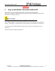
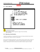
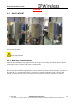
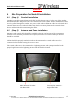
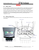
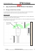
Table Of Contents
- IMPORTANT
- Legal Terms Governing This Document
- 1 OVERVIEW
- 2 PRE-INSTALLATION
- (Step 3) MOUNTING THE NODE B BRACKET
- 4 Site Preparation for Node B Installation
- 5 (Step 10) PHYSICAL INSTALLATION OF THE NODE B
- 5.1 Placing the Node B into the Rack
- 5.2 Service Area Interfaces
- 5.3 (Step 6) Grounding Installation and Inspection
- 5.4 Cable Clamp Seal
- 5.5 Connecting Power to the Node B
- Backhaul Connections to INC
- 5.7 Alarm Connections
- 5.8 Replacement of the Seal cable clamp
- 5.9 Conduit Pivot Bracket Securing
- 5.10 Closing the Door and securing the NodeB
- 5.11 GPS
- 6 (Step 11) Power up and Initial Setup of Node B
- 8
- 8 (Step 12) SOFTWARE INSTALLATION
- 9 (Step 13) On Air final check
- 10 Operation & Maintenance

Node B Installation Guide
DRAFT
17 July, 2001 IPWireless Proprietary
IT IS ILLEGAL TO MAKE COPIES OF THIS DOCUMENT WITHOUT EXPRESS PERMISSION BY IPWIRELESS
11
3 (Step 3) MOUNTING THE NODE B BRACKET
There are three ways of installing the Node B – Wall, Pole and Rack Mounts.
This section explains the three different mounting types with the installation and powering
procedure for each type of mount.
PRECAUTIONS
The following precautions and checks are applicable to all mounting types.
Leave blanking plugs over all connectors until they have been connected to the appropriate
cabling. These plugs are specially fitted to keep moisture and contaminates out of the unit.
Connectors have been manufactured to fit their specific cables. Do not modify or force
connectors.
Check Site Plans for engineering approval.