
User Manual
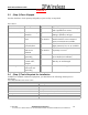
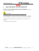
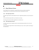
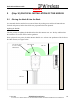
Table Of Contents
- IMPORTANT
- Legal Terms Governing This Document
- 1 OVERVIEW
- 2 PRE-INSTALLATION
- (Step 3) MOUNTING THE NODE B BRACKET
- 4 Site Preparation for Node B Installation
- 5 (Step 10) PHYSICAL INSTALLATION OF THE NODE B
- 5.1 Placing the Node B into the Rack
- 5.2 Service Area Interfaces
- 5.3 (Step 6) Grounding Installation and Inspection
- 5.4 Cable Clamp Seal
- 5.5 Connecting Power to the Node B
- Backhaul Connections to INC
- 5.7 Alarm Connections
- 5.8 Replacement of the Seal cable clamp
- 5.9 Conduit Pivot Bracket Securing
- 5.10 Closing the Door and securing the NodeB
- 5.11 GPS
- 6 (Step 11) Power up and Initial Setup of Node B
- 8
- 8 (Step 12) SOFTWARE INSTALLATION
- 9 (Step 13) On Air final check
- 10 Operation & Maintenance

Node B Installation Guide
DRAFT
17 July, 2001 IPWireless Proprietary
IT IS ILLEGAL TO MAKE COPIES OF THIS DOCUMENT WITHOUT EXPRESS PERMISSION BY IPWIRELESS
17
4.5 (Step 9) External Alarms
If local alarms are to be utilized for a terminal block has been provided on the Node B
termination panel. The specifications for those interface requirements are below.
4.5.1 Alarm Input Specification
The alarm inputs from the Node B Patch board to the digital board shall be TTL levels and active
high.
The external alarm inputs shall be opto-isolated current loops.
The voltage and currents shall be supplied by the external source.
4.5.2 Alarm Output Specification
The alarm outputs from the digital board to the Node B Patch Board shall be TTL levels and
active high. .
The external alarm outputs shall be isolated normally-open relay contacts capable of switching at
least 100mA DC.