
User Manual
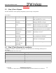
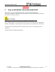
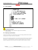
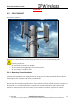
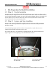
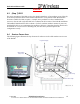
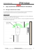
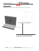
Table Of Contents
- IMPORTANT
- Legal Terms Governing This Document
- 1 OVERVIEW
- 2 PRE-INSTALLATION
- (Step 3) MOUNTING THE NODE B BRACKET
- 4 Site Preparation for Node B Installation
- 5 (Step 10) PHYSICAL INSTALLATION OF THE NODE B
- 5.1 Placing the Node B into the Rack
- 5.2 Service Area Interfaces
- 5.3 (Step 6) Grounding Installation and Inspection
- 5.4 Cable Clamp Seal
- 5.5 Connecting Power to the Node B
- Backhaul Connections to INC
- 5.7 Alarm Connections
- 5.8 Replacement of the Seal cable clamp
- 5.9 Conduit Pivot Bracket Securing
- 5.10 Closing the Door and securing the NodeB
- 5.11 GPS
- 6 (Step 11) Power up and Initial Setup of Node B
- 8
- 8 (Step 12) SOFTWARE INSTALLATION
- 9 (Step 13) On Air final check
- 10 Operation & Maintenance

Node B Installation Guide
DRAFT
17 July, 2001 IPWireless Proprietary
IT IS ILLEGAL TO MAKE COPIES OF THIS DOCUMENT WITHOUT EXPRESS PERMISSION BY IPWIRELESS
18
5 (Step 10) PHYSICAL INSTALLATION OF THE NODE B
5.1 Placing the Node B into the Rack
It is assumed that the unit has been removed from the packing crate and that all materials are
checked and present, further that all the site preparation has been planned.
Sighting the NodeB
The first priority in sighting the NodeB is that the GPS antenna can ‘see’ the sky and therefore
the satellites. See section 4.4 for further guidance.
From a physical view point, the GPS antenna should ‘see’ at least a 90º quadrant of the ski above
the GPS antenna, see figure below.
<Detail to be added>
GPS Antenna Field
of Vision
- No
Obstructions
Min 1m
Min 1m
GPS Antenna