
User Manual
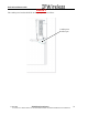
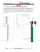
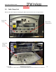
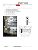
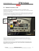
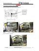
Table Of Contents
- IMPORTANT
- Legal Terms Governing This Document
- 1 OVERVIEW
- 2 PRE-INSTALLATION
- (Step 3) MOUNTING THE NODE B BRACKET
- 4 Site Preparation for Node B Installation
- 5 (Step 10) PHYSICAL INSTALLATION OF THE NODE B
- 5.1 Placing the Node B into the Rack
- 5.2 Service Area Interfaces
- 5.3 (Step 6) Grounding Installation and Inspection
- 5.4 Cable Clamp Seal
- 5.5 Connecting Power to the Node B
- Backhaul Connections to INC
- 5.7 Alarm Connections
- 5.8 Replacement of the Seal cable clamp
- 5.9 Conduit Pivot Bracket Securing
- 5.10 Closing the Door and securing the NodeB
- 5.11 GPS
- 6 (Step 11) Power up and Initial Setup of Node B
- 8
- 8 (Step 12) SOFTWARE INSTALLATION
- 9 (Step 13) On Air final check
- 10 Operation & Maintenance

Node B Installation Guide
DRAFT
17 July, 2001 IPWireless Proprietary
IT IS ILLEGAL TO MAKE COPIES OF THIS DOCUMENT WITHOUT EXPRESS PERMISSION BY IPWIRELESS
27
5.6 Backhaul Connections to INC
The Node B currently requires one 100 BaseT connection to a serving INC. Future
enhancements will enable (4) T1's for connection to a serving INC. The connections are labeled
and shown in the figure below.
If the Node B is in not in the same site location as the serving INC, there must be no greater than
a 5 millisecond delay on the backhaul connection. This can be provided by microwave or land
based facilities with a very high reliability rate of 99.9995%.
Terminate the Ethernet cables with RJ48 connectors and strip the wire to allow proper
connection to the earth bar. Test the continuity for the Ethernet cables with test equipment
consisting of a main and a remote unit.
The termination for these interfaces is specified within the datasheets for the interfaces. The
specification for both cables should be CAT5 - 4 pair, screened cable, recommended Alcatel
LANmark-5 F
2
TP or equivalent.
Power
Terminals
Protective
Cover
Backhaul
T1
(
4
)
Backhaul
100BaseT