
User Manual
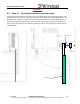
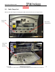
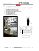
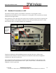
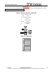
Table Of Contents
- IMPORTANT
- Legal Terms Governing This Document
- 1 OVERVIEW
- 2 PRE-INSTALLATION
- (Step 3) MOUNTING THE NODE B BRACKET
- 4 Site Preparation for Node B Installation
- 5 (Step 10) PHYSICAL INSTALLATION OF THE NODE B
- 5.1 Placing the Node B into the Rack
- 5.2 Service Area Interfaces
- 5.3 (Step 6) Grounding Installation and Inspection
- 5.4 Cable Clamp Seal
- 5.5 Connecting Power to the Node B
- Backhaul Connections to INC
- 5.7 Alarm Connections
- 5.8 Replacement of the Seal cable clamp
- 5.9 Conduit Pivot Bracket Securing
- 5.10 Closing the Door and securing the NodeB
- 5.11 GPS
- 6 (Step 11) Power up and Initial Setup of Node B
- 8
- 8 (Step 12) SOFTWARE INSTALLATION
- 9 (Step 13) On Air final check
- 10 Operation & Maintenance

Node B Installation Guide
DRAFT
17 July, 2001 IPWireless Proprietary
IT IS ILLEGAL TO MAKE COPIES OF THIS DOCUMENT WITHOUT EXPRESS PERMISSION BY IPWIRELESS
28
The pin-outs for the external Ethernet & T1 interfaces are given in the following tables. Source:
http://www.dcbnet.com/notes/9611t1.html
Figure 3: Ethernet Pin-outs using RJ45
1 RX + White w/Green
2 RX - Green
3 TX + White w/Orange
4 Blue
5 White w/Blue
6 TX - Orange
7 White w/Brown
8 Brown
Figure 4: T1 Pin-outs
1 Receive (ring)
2 Receive (tip)
3 Not Used
4 Transmit (ring)
5 Transmit (tip)
6 Not Used
7 Not Used
8 Not Used