
User Manual
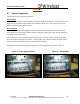
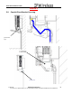


Table Of Contents
- IMPORTANT
- Legal Terms Governing This Document
- 1 OVERVIEW
- 2 PRE-INSTALLATION
- (Step 3) MOUNTING THE NODE B BRACKET
- 4 Site Preparation for Node B Installation
- 5 (Step 10) PHYSICAL INSTALLATION OF THE NODE B
- 5.1 Placing the Node B into the Rack
- 5.2 Service Area Interfaces
- 5.3 (Step 6) Grounding Installation and Inspection
- 5.4 Cable Clamp Seal
- 5.5 Connecting Power to the Node B
- Backhaul Connections to INC
- 5.7 Alarm Connections
- 5.8 Replacement of the Seal cable clamp
- 5.9 Conduit Pivot Bracket Securing
- 5.10 Closing the Door and securing the NodeB
- 5.11 GPS
- 6 (Step 11) Power up and Initial Setup of Node B
- 8
- 8 (Step 12) SOFTWARE INSTALLATION
- 9 (Step 13) On Air final check
- 10 Operation & Maintenance

Node B Installation Guide
DRAFT
17 July, 2001 IPWireless Proprietary
IT IS ILLEGAL TO MAKE COPIES OF THIS DOCUMENT WITHOUT EXPRESS PERMISSION BY IPWIRELESS
30
5.7 Alarm Connections
The description of the alarms is as follows
Alarm Inputs
The alarm inputs from the Node B Patch board to the digital board shall be TTL levels and active
high. The external alarm inputs shall be opto-isolated current loops. The voltage and currents
shall be supplied by the external source.
Alarm Outputs
The alarm outputs from the digital board to the Node B Patch Board shall be TTL levels and
active high. The external alarm outputs shall be isolated normally-open relay contacts capable of
switching at least 100mA DC.
The connectors are 12way (alarm inputs) and 2ways for the alarm outputs, 2.5mm pitch header
that mate with the supplied cable mount – tension clamp. The cables should be stripped 5-6mm
and inserted into the connector prior to mating with the NodeB.
The signals are paired starting from the right, pin1 is the right-hand-side on each connector.
Figure 4 : Alarm Outputs (2x2)
Figure 4 : Alarm Inputs