
Installation Guide


Node B Installation Guide
Version 5.0.0 Page 28 of 37
Notes:
Points to remember when installing Category 5 cables for the Node B 100Base T
Ethernet Backhaul.
1. Do not kink the cable as the pairs are twisted to support 100Mhz operation and splitting the
pairs could reduce the performance of the cable.
2.
When installing the RJ45 plugs onto the cable ensure pairs are untwisted to the minimum
and that the cable sheath is clamped within the connector. Again this is to ensure the
performance of the cable is not reduced.
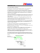
The pin-outs for the external Ethernet interfaces are given in the following table & figure.
Source: http://www.dcbnet.com/notes/9611t1.html
Figure 6-16 : Ethernet Pin-outs using RJ45
1 RX +
White w/Green
2 RX -
Green
3 TX +
White w/Orange
4
Blue
5
White w/Blue
6 TX -
Orange
7
White w/Brown
8
Brown
Figure 6-17 : Ethernet Pin-outs using RJ45
Table 6-5 : T1/E1 Pin-outs
T1 Pinouts Cable E1 Pinouts
1
Rx (ring) White w/Green Rx (ring)
1
2
Rx (tip) Green Rx (tip)
2
3
Not used White w/Orange Not used
3
4
Tx (ring) Blue Tx (ring)
4
5
Tx (tip) White w/Blue Tx (tip)
5
6
Not used Orange
Not used
6
7
Not used White w/Brown Not used
7
8
Not used Brown Not used
8
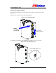
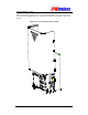
E3/T3 Connections – (Tx + Rx)
Feed the cables through the cables glands external from the enclosure before feeding the cable
through the appropriate gland hole at the base of the Node B.
Terminate the E3/T3 cables with BNC connectors and secure the cable gland to the Node B. Test
the continuity for the Ethernet cables with test equipment consisting of a main and a remote unit.