
Installation Guide


Node B Installation Guide
Version 5.0.0 Page 29 of 37
The termination for these interfaces is specified within the datasheets for the interfaces. The
specification for both cables should be 75.
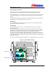
E1/T1 Connections – (1 to 4)
Feed the 4 E1/T1 cables through the paired cables glands (ie. dual elastomer insert) external
from the enclosure before feeding the cable through the appropriate gland hole at the base of the
Node B.
Terminate the E1/T1 cables with RJ45 connectors and secure the cable gland to the Node B.
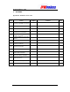
Test the continuity for the Ethernet cables with test equipment consisting of a main and a remote
unit. The pinouts for this interface are shown in the table above.
The termination for these interfaces is specified within the datasheets for the interfaces. The
specification for both cables should be CAT5 - 4 pair, screened cable, recommended Alcatel
LANmark-5 F2TP or equivalent.
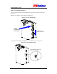
Step 12 Antenna Cabling - Installation
Antennas and coaxial cable should be available at the site, and are part of the construction
checklist and general assumptions.
Two antennae per Node B are optimum, allowing receiver diversity, therefore two coaxial cables
per Node B are needed in this case. Diversity can be via polarization, in which case two feeder
runs to the same antenna are needed, feeding oppositely polarised sectors in the same physical
enclosure.
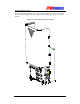
Cables should be properly marked to indicate what antenna the coaxial cables are to be
connected to the Node B serving the sector or area.
In the case where only one feeder / antenna is being used, this must be connected to the left
hand connector when viewed from the front of the Node B.
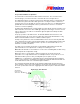
The following installation describes the position of the antenna ports and designations.
Figure 6-18 : Antenna Connections
Main Antenna Tx & Rx –
Left Hand Side
- DIN 7/16 - Female
Diversity Rx Antenna
- Right Hand Side
- DIN 7/16 - Female
–