OEM TD-CDMA PCI Express Module Integration OEM TD-CDMA PCI Express Mini Module Integration Guide V01.
OEM TD-CDMA PCI Express Module Integration Contents 1 2 3 General ................................................................................................................ 4 1.1 Approvals and Dates ............................................................................................................... 4 1.2 Change Record ....................................................................................................................... 4 1.3 Acronyms ...............................
OEM TD-CDMA PCI Express Module Integration 4.1.7 5 Regulatory Information – Model AAU 2.5GHz Band. ......................................... 18 5.1 6 PEM in Laptop ............................................................................................................... 17 FCC Requirements for North America .................................................................................. 18 5.1.1 Compliance with FCC Rules and Regulations .........................................................
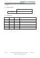
OEM TD-CDMA PCI Express Module Integration 1 1.1 General Approvals and Dates Approval Date W. J. Jones 1.2 Change Record Date Version Author 30/08/2013 01.00 PFW New Document. 30/09/2013 01.
OEM TD-CDMA PCI Express Module Integration 1.3 Acronyms Term Definition TD-CDMA Time Division – Code Division Multiple Access MPE Maximum Permissible Exposure OEM Original Equipment Manufacturer PCIe PCI Express PCI SIG PCI Special Interest Group PEM PCI Express Mini SIM Subscriber Identity Module USB Universal Serial Bus 1.
OEM TD-CDMA PCI Express Module Integration 2 Introduction This document describes the method of integrating the General Dynamics Broadband TD-CDMA PCI Express Mini module into an OEM product. 2.1 Scope of Document This document applies to the following General Dynamics Broadband TD-CDMA PCI Express Mini modules. 2.2 Model: AAU.
OEM TD-CDMA PCI Express Module Integration 3 Module Connections 3.1 PCI Express Mini Interface (J1) The General Dynamics Broadband TD-CDMA PCI Express Mini module is provided with a 52 pin edge connector for connection to the external application. This connection supports the following interface types and these are described below. The pinout is shown in Annex 1. 3.1.1 Universal Serial Bus The PCI Express edge connector provides a USB 2.0 interface, this interface supports low speed (1.
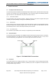
OEM TD-CDMA PCI Express Module Integration 3.4 Management of Radio Receiver Self-Interference The General Dynamics Broadband TD-CDMA PEM is supplied as a stand-alone PCI Express Card, or can be mounted on an General Dynamics Broadband TD-CDMA Adaptor card. It is the customer who then has to integrate the PEM - either on a Host Circuit Board, or mounted within their own Host Equipment, at which point, the location of the antennas which connect to the PEM are outside of General Dynamics Broadband control.
OEM TD-CDMA PCI Express Module Integration f. 3.4.2 Designers must be aware that PCB connectors contain exposed metal which will radiate and design and shield accordingly. Provision should be provided for options to link connector shields to PCB ground if the best way is not clear, or is not known. Unit Level The ideal way to suppress RF interferers is to enclose all of the active circuitry in a metal can without holes or joins.
OEM TD-CDMA PCI Express Module Integration b. If possible, specify a metal enclosure for the Host Equipment if the PEM’s antennas have to be, or might be mounted in close proximity. c. Provide an RF connection point on the Host Equipment to which the customer can connect an alternative remote antenna and make the remote antenna available as an approved accessory. d.
OEM TD-CDMA PCI Express Module Integration 4 Mechanical The General Dynamics Broadband TD-CDMA PCI Express Mini module is designed to be installed in a PCI Express compliant slot capable of holding an F1 full size mini card.
OEM TD-CDMA PCI Express Module Integration 4.1 Thermal Management The General Dynamics Broadband TD-CDMA PCI Express Mini module integration shall be in accordance with the PCISIG thermal requirements. This section describes the thermal specifications for the General Dynamics Broadband TD-CDMA PCI Express Mini Card plus Adaptor and provides recommendations for thermal cooling schemes within the two configurations and covers the following: 4.1.
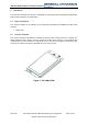
OEM TD-CDMA PCI Express Module Integration Figure 5: PEM Unit Assembly Bottom 4.1.2 PEM and TD-CDMA Adaptor Thermal Specification Parameter Rating Comments Power Dissipation: 8.0 Watts @ 24.0VDC Ambient Air Specification: -30°C to +70°C PCI Standard 1.2 -30C to +65C Maximum Temperature Rise +25°C PEM PCB Construction 10 Layer ½ oz copper No components fitted to bottom.
OEM TD-CDMA PCI Express Module Integration Figure 6: PEM and Adapter Assembly - Top Figure 7: PEM and Adaptor Assembly - Bottom May 2013 General Dynamics Broadband Proprietary and Confidential Subject to Non Disclosure Agreement Page 14 of 20
OEM TD-CDMA PCI Express Module Integration 4.1.3 Physical Thermal Arrangement – PEM and Adaptor This section describes the thermal arrangement of the PEM and Adaptor assembly. The arrangement is architected to maximize the heat transfer from the PEM to the Adaptor Card by creating a low thermal resistance between the PEM and the Adapter board. A similar scheme will be described for laptop installations. a) The layer structure of PCB – PEM see section 3.
OEM TD-CDMA PCI Express Module Integration 4.1.4 PEM and Adaptor Simulated Environment within theoretical enclosure The PEM and Adaptor has been thermally simulated with the following sectioned enclosure to maintain a maximum 20°C temperature rise above ambient, i.e. max 90°C ambient.
OEM TD-CDMA PCI Express Module Integration 4.1.5 Recommendations for thermal cooling schemes This section specifies the recommendations for the installations for the two configurations below. 4.1.6 o PEM and Adaptor Configurations. o PEM in laptop Configurations. PEM and Adaptor This configuration is planned to be within a die-cast enclosure and the following features are recommended to add to the construction.
OEM TD-CDMA PCI Express Module Integration 5 Regulatory Information – Model AAU 2.5GHz Band. NOTE: This module is not suitable for installation in products that are required to meet ATEX or other Hazardous Location requirements. 5.1 FCC Requirements for North America 5.1.
OEM TD-CDMA PCI Express Module Integration 5.1.4 Antenna Gains for Standalone Operation To comply with FCC rules relating to maximum RF power and RF Exposure, the maximum antenna gain including cable loss for mobile operation when not co-located with other transmitters must not exceed the following limits.. Band Antenna Gain 2.5GHz EBS/BRS 8.5dBi Please refer to the FCC Grant of Certification.
OEM TD-CDMA PCI Express Module Integration 6 Annex 1: PCI Express Mini Edge Connector Pinout Pin Name Pin Name 51 Reserved 52 +3.3Vaux 49 PCIe - Reserved, rMII - ETH_MDC 50 GND 47 PCIe - Reserved, rMII - ETH_MDIO 48 +1.5V 45 PCIe - Reserved, rMII - ETH_Tx_EN 46 LED_WPAN# 43 GND 44 PCIe - LED_WLAN#, rMII - ADAPTOR_SENSE_2 41 +3.3Vaux 42 LED_WWAN# 39 +3.