
User's Manual


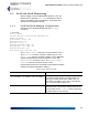

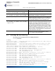

Table Of Contents
- Chapter 1 Introduction
- Chapter 2 Mesh Point CLI and Administrative Access
- Chapter 3 Networking and Radio Configuration
- 3.1 Network Interfaces
- 3.2 Network Bridging
- 3.2.1 Bridging Configuration
- 3.2.2 FastPath Mesh Bridging
- 3.2.3 Fine-tuning FastPath Mesh Network Performance
- 3.2.3.1 Selecting the FastPath Mesh Multicast Transmit Mode
- 3.2.3.2 Setting the FastPath Mesh Packet Interval
- 3.2.3.3 Setting the FastPath Mesh Transmit Control Level
- 3.2.3.4 Setting Multicast Video Clamping Thresholds
- 3.2.3.5 Setting Mesh Routing Reactivity
- 3.2.3.6 Setting Mesh Packet Time To Live
- 3.2.3.7 Viewing Current Mesh Performance Parameters
- 3.2.3.8 Frame Processor Parameters
- 3.2.4 STP Bridging
- 3.3 Global Radio Settings
- 3.4 Individual Radio Settings
- 3.4.1 Radio Band, Short Preamble, Guard Interval
- 3.4.2 Channel Selection
- 3.4.3 Distance, Beacon Interval, Noise Immunity
- 3.4.4 Network Type, Antenna Gain, Tx Power
- 3.4.5 MIMO
- 3.4.6 STBC
- 3.4.7 Channel Lock and Other Channel Selection Features
- 3.4.8 DFS, TDWR, and Channel Exclusion
- 3.4.9 Radio BSS Settings
- 3.4.9.1 BSS Radio, BSS Name and SSID
- 3.4.9.2 WDS Bridging or AP Infrastructure Configuration
- 3.4.9.3 BSS State, SSID Advertising and Drop Probe Requests
- 3.4.9.4 BSS STA Idle Timeout and 802.11g-Only Settings
- 3.4.9.5 BSS Unicast Transmission Rate Settings
- 3.4.9.6 BSS WMM QoS Setting
- 3.4.9.7 BSS Fragmentation and RTS Thresholds
- 3.4.9.8 BSS DTIM Beacon Countdown
- 3.4.9.9 BSS VLANs Settings
- 3.4.9.10 BSS Fortress Security Zone
- 3.4.9.11 FastPath Mesh BSS Cost Offset
- 3.4.9.12 BSS Multicast Settings
- 3.4.9.13 Bridging MTU and Beacon Encryption
- 3.4.9.14 BSS Description
- 3.4.9.15 BSS Wi-Fi Security Configuration
- 3.4.10 Antenna Tracking / Rate Monitoring
- 3.4.11 ES210 Mesh Point STA Settings and Operation
- 3.4.11.1 STA Radio, Name, SSID and SSID Roaming
- 3.4.11.2 STA State
- 3.4.11.3 STA Unicast Transmission Rate Settings
- 3.4.11.4 STA Background Scanning
- 3.4.11.5 STA WMM QoS Setting
- 3.4.11.6 STA Fragmentation and RTS Thresholds
- 3.4.11.7 STA Multicast Rate
- 3.4.11.8 STA Description
- 3.4.11.9 STA Wi-Fi Security Configuration
- 3.4.11.10 Editing or Deleting a STA Interface Connection
- 3.4.11.11 Establishing a STA Interface Connection
- 3.4.11.12 ES210 Station Access Control Lists
- 3.5 Local Area Network Configuration
- 3.6 Time and Location Configuration
- 3.7 GPS and Location Configuration
- 3.8 DHCP and DNS Services
- 3.9 Ethernet Interfaces
- 3.10 Quality of Service
- 3.11 VLANs Implementation
- 3.12 ES210 Mesh Point Serial Port Settings
- 3.13 Mesh Viewer Protocol Settings
- Chapter 4 Network Security, Authentication and Auditing
- 4.1 Fortress Security Settings
- 4.1.1 Operating Mode
- 4.1.2 FIPS Settings
- 4.1.3 MSP Encryption Algorithm
- 4.1.4 Encrypted Data Compression
- 4.1.5 MSP Key Establishment
- 4.1.6 MSP Re-Key Interval
- 4.1.7 Key Beacon Interval
- 4.1.8 Fortress Legacy Devices
- 4.1.9 Encrypted Zone Cleartext Traffic
- 4.1.10 Encrypted Zone Management Settings
- 4.1.11 Authorized Wireless Client Management Settings
- 4.1.12 Turning Mesh Point GUI Access Off and On
- 4.1.13 SSH Access to the Mesh Point CLI
- 4.1.14 Blackout Mode
- 4.1.15 Allow Cached Credentials
- 4.1.16 Fortress Access ID
- 4.2 Digital Certificates
- 4.3 Access Control Entries
- 4.4 Internet Protocol Security
- 4.5 Authentication and Timeouts
- 4.5.1 Authentication Servers
- 4.5.2 Internal Authentication Server
- 4.5.2.1 Basic Internal Authentication Server Settings
- 4.5.2.2 Certificate Authority Settings
- 4.5.2.3 Global User and Device Authentication Settings
- 4.5.2.4 Local 802.1X Authentication Settings
- 4.5.2.5 OCSP Authentication Server Settings
- 4.5.2.6 OCSP Cache Settings and Management
- 4.5.2.7 Internal Authentication Server Access Control Lists
- 4.5.3 User Authentication
- 4.5.4 Client Device Authentication
- 4.5.5 Session Idle Timeouts
- 4.6 ACLs and Cleartext Devices
- 4.7 Remote Audit Logging
- 4.8 Wireless Schedules
- 4.1 Fortress Security Settings
- Chapter 5 System Options, Maintenance and Licensing
- Chapter 6 System and Network Monitoring
- Index
- Glossary

Fortress ES-Series CLI Guide: System and Network Monitoring
187
NOTE:
Bridge
Links
are not rele-
vant to Mesh Point mod-
els that do not contain
radios.
6.2.2 Viewing Bridging Links
On Mesh Points equipped with one or more radios (refer to
Table 1.1 on page 3), view current wireless bridging links with
show bridgelinks:
# show bridgelinks
Rate Signal
Radio MAC Address (Mbps) Strength Device ID State
------ ----------------- ------ -------- ---------------- --------------
radio1 00:14:8c:1e:ab:80 54 -70 333300192f1d562f forwarding_all
radio1 00:14:8c:1e:ac:40 54 -75 3333001ca5211b96 forwarding_all
radio1 00:14:8c:1e:c6:40 54 -76 33330016df733cd1 forwarding_all
radio1 00:14:8c:1e:c6:80 54 -82 333300148c1e33c1 forwarding_all
radio1 00:14:8c:1e:c6:c0 54 -72 3333001ca5fe351d forwarding_all
radio1 00:14:8c:1e:c7:40 54 -71 333300148c1ec740 forwarding_all
radio1 00:14:8c:1e:d3:00 54 -72 3333001a44eb67d2 forwarding_all
radio1 00:14:8c:1e:d4:c0 54 -72 333300148c1ed4c0 forwarding_all
radio1 00:14:8c:1e:eb:00 54 -73 none forwarding_all
radio1 00:14:8c:1e:eb:80 54 -69 none forwarding_all
radio1 00:14:8c:1e:eb:c0 54 -78 none forwarding_all
radio1 00:14:8c:1e:ed:40 54 -68 none forwarding_all
radio1 00:14:8c:1e:ed:c0 54 -75 none forwarding_all
--- Total WDS bridge links: 14
Radio -
the radio on which the BSS forming the bridging link
is configured
MAC Address - the MAC address of the connected node
Rate - the maximum data transmission rate of the link in
megabits per second.
Because of the radio enhancements and traffic handling
efficiencies defined in the newer standard, bridging links
between radios configured to use 802.11n can show Rate
values higher than the Maximum Rate configured for either
individual interface (refer to Section 3.4.9)
Signal Strength - the strength of the RF signal of the link,
in decibels referenced to milliwatts
Device ID - the unique hexadecimal Fortress-generated
identifier which provides device authentication on the Mesh
Point-secured network of the connected network node
During normal operation, a Device ID of
none is shown for
a Mesh Point that has been detected but for which a Device
ID has not been established (because key establishment is
not yet complete or for a unidirectional link). A Device ID of
none can also indicate mismatched Access IDs between
the current and connected Mesh Points (Section 4.1.16).
State - the bridging status of the connected network node.
Possible values and meanings depend on the Mesh Point’s
current Bridging Mode setting (refer to Section 3.2.1):