
User's Manual
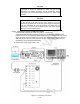
Table Of Contents

4-18
: The "more" softkey may have to
i.
j. C" softkey.
" softkey.
e
o. ursor to the Pos (Position) position and depress the "move up" or "move
5. Setup the URC-200 (V2) as follows:
eeds 330mA, a problem exists in the transceiver. Turn off the power
c.
d. Select METER of this manual.
6.
a. cursor to the Gen RF Out position and select GEN. Move the cable from the
t
to -80.0 dBm. Verify at least one bar is present.
d verify fourteen 14 bars are present on the URC-
b.
4-2.3. TRA
Th cy
accuracy,
ues, it must be sent to General
r.
g. Depress the DISP (Display) key on the R2600 panel. Move the cursor to the Meter
position and depress the "AC VOLTS" softkey. Note
be depressed for the "AC VOLTS" softkey to be displayed.
h. Move the cursor to the Range position and depress the "AUTO" softkey.
Move the cursor to the Display position and depress the "EXT SCOPE" softkey.
Move the cursor to the Coupling position and depress the "A
k. Move the cursor to the Trigger position and depress the "AUTO" softkey.
l. Move the cursor to the Trigger Lvl (Trigger Level) position and enter 500 from the
keypad.
m. Move the cursor to the Horiz (Horizontal) position and depress the "500 us
Note: The "more" softkey may have to be depressed for the "500 us" softkey to be
displayed.
n Move the cursor to the Vert (Vertical) position and depress the "1 V" softkey. Note: Th
"more" softkey may have to be depressed for the "1 V" softkey to be displayed.
Move the c
down" softkeys as appropriate to center the displayed scope screen trace. Note: The
TUNING knob on the R2600 panel may be used in lieu of the "move up" or "move
down" softkeys.
p. Adjust both the SQUELCH and VOLUME controls on the front panel to their maximum
CCW positions.
a. Turn the transceiver on and note the input current. It should be approximately 240mA.
If the current exc
and troubleshoot the transceiver.
b. Set the channel 3 for the preset frequency as listed in Table 4-3. Adjust the URC-200
(V2) for the following. Note: Information on presetting the URC-200 (V2) is given in
Paragraph 2-3.2 located in Section 2 of this manual.
FM, PT, SCN OFF, BCN OFF, SPKR ON, CH 3
Adjust the SQ (Squelch) control fully counter-clockwise, past its detent, to the OFF
position.
MODE per Paragraph 2-3.1.5 located in Section 2
Signal-Strength Meter Measurement:
Move the
RF IN/OUT connector to the GEN OUT connector. Position the cursor to the Outpu
Lvl position and enter a signal level
Readjust the Output Lvl to 0dBm an
200 (V2) display with the possibility that the 14th bar may be flickering on and off.
Move the cursor back to the Gen RF Out position and select RF IN/OUT. Move the
cable back to the RF IN/OUT connector.
NSMITTER TESTS
e following tests evaluate the
performance of the XMT circuits. Tests include frequen
output power, PT/CT modulation, modulation distortion, and beacon. If the transceiver
fails a
ny of the tests, or if it cannot be adjusted to specified val
Dynamics C4 Systems for repai