CG-1309 REV C FEB 2006 OPERATION & MAINTENANCE MANUAL UP/DN CONVERTER L-BAND LT-3600 SERIES EXPORT CONTROL WARNING - Do not disclose this document or its contents to non-U.S. Persons, or transmit this document or its contents outside the United States without the written permission of Vertex Communications Corporation and required U.S.
Integrated L-Band Up/Dn Converter LT3600 CG-1309 WARRANTY VertexRSI warrants its products for a period of two (2) years from the date of shipment to be free from defects caused by faulty materials or poor workmanship. The terms and conditions of this warranty are as follows • The purchaser must notify VertexRSI promptly upon discovery of such defect.
Integrated L-Band Up/Dn Converter LT3600 CG-1309 TABLE OF CONTENTS Section 1 1.0 1.1 1.2 1.3 1.4 1.5 1.6 1.7 1.8 Introduction.............................................................................................................................. 6 Safety Information ................................................................................................................... 6 General Introduction ................................................................................................
Integrated L-Band Up/Dn Converter LT3600 Section 4 CG-1309 Serial Command Set .............................................................................................. 20 4.0 4.1 4.2 General.................................................................................................................................... 20 LT-3600 Serial Interface..........................................................................................................20 Communication Protocol ....................
Integrated L-Band Up/Dn Converter LT3600 CG-1309 APPENDICES A B C Technical Manual Revision History ....................................................................................... 26 CCA Software Revision History............................................................................................. 26 Display Panel Software Revision History...............................................................................
Integrated L-Band Up/Dn Converter LT3600 SECTION 1 CG-1309 General Information 1.0 INTRODUCTION This manual contains installation, operation, and maintenance information for the Integrated L-Band Up/Dn Converter manufactured by VertexRSI, Longview, Tx. Information is organized according to section. Within each section the pages, figures and tables are numbered by section and by order of appearance within the section.
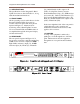
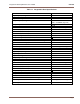
Integrated L-Band Up/Dn Converter LT3600 1.4 SPECIFICATIONS The specifications for the Integrated L-Band Up/Dn Converter are listed in Table 1-1, along with the mechanical dimensions. 1.5 FRONT PANEL All the operating controls and indicators for the Integrated L-Band Up/Dn Converter are located on the front panel. The front panel is depicted in Figure 1-1.
Integrated L-Band Up/Dn Converter LT3600 CG-1309 1.8 Part Number Configuration The Part Number Selection Chart shows configuration options that are set at the factory prior to shipment. The voltage output to J4 and J10 may be changed as required by the customer, however this requires removal of the cover and resetting internal jumper connections. This should be performed by qualified personnel. Base Number 201667 - 1st Digit IF Operation 1 70 MHZ 2nd Digit L-Band 1 Std.
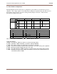
Integrated L-Band Up/Dn Converter LT3600 CG-1309 Table 1-1 Integrated L-Band Specifications UPCONVERTER Input Frequency Range Input Impedance Input Level Range Output Frequency Range Output Impedance Output Return Loss Conversion Gain Gain Linearity (over 10 dB) Gain Linearity (over 20 dB) Gain Stability (0 to +50 °C) Amplitude Response (over any 36 MHz) Amplitude Response (over 875 MHz) Output Power (1 dB GCP) 3rd Order Intermodulation (for 2 car.
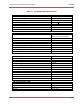
Integrated L-Band Up/Dn Converter LT3600 CG-1309 Table 1-1 Integrated L-Band Specifications OPTIONAL INTERNAL REFERENCE Reference Frequency Stability (0 to +50 °C) Aging per Day Output Level (rear panel) Phase Noise @ 10 Hz 100 Hz 1 kHz 10 kHz UPCONVERTER and DOWNCONVERTER Synthesizer Configuration Tx Synthesizer and Rx Synthesizer Step Size Parameter Memory Storage L-Band Output Phase Noise: at 100 Hz Offset at 1 kHz Offset at 10 kHz Offset at 100 kHz Offset at 1 MHz Offset 10.
Integrated L-Band Up/Dn Converter LT3600 CG-1309 Table 1-1 Integrated L-Band Specifications INTERFACE AND CONNECTORS Voltage (auto-ranging) Internal Electronics (Power) StarSwitch Interface Connectors (Options) Remote Serial Interface: Standard: RS-422/RS-485 (J7) External SSPB Monitor and Control (J6) DC Output to LNB on J4 (coaxial) (Options) DC Output to SSPB on J10 (coaxial) (Options) Operational Temperature Range 115/230 VAC +15% 25 watts DB-15 (Female) DB-9 (Male) DB-9 (Female) 22 VDC @ 0.
Integrated L-Band Up/Dn Converter LT3600 CG-1309 SECTION 2 Installation 2.0 INTRODUCTION 2.4.1 Power Input This section defines the installation requirements by which the Integrated L-Band Up/Dn Converter will meet the published specifications. This connector is an IEC 320-C14 male and will accept any compatible mating connector. The power cord supplied as standard with the unit is equipped with a NEMA 5-15P male plug at the opposite end and is compatible with most 115 VAC supplies.
Integrated L-Band Up/Dn Converter LT3600 2.4.6 External 10 MHz Input (J2) This connector is a BNC female. The male mate (not supplied) should be compatible with the 50-ohm coax used to connect to the system. 2.4.7 SSPB Interface (J6) This connector is a 9-pin female miniature type “D” connector with standard #4-40 female screw-lock hardware mounting. The mating shell, pins, and strain relief are not supplied. Outputs are open collector and inputs have internal 1K full PS to +5V.
Integrated L-Band Up/Dn Converter LT3600 CG-1309 SECTION 3 Operation 3.0 INTRODUCTION The Up/Down Converter can be controlled from the front panel or remotely via a serial bus located on the rear panel of the converter. Various menus are available for EDIT and DISPLAY purposes. See Figure 3-2 for a listing of the menus. Section 4 gives a complete description of the bus commands and conventions for operating the converter remotely.
Integrated L-Band Up/Dn Converter LT3600 CG-1309 DISPLAY RefOsc: OK Slope Factor: EDIT Ofst:127 0 dB Unit Address: xx xx = 422 Mode LCL RefOsc: OK Slope Factor: Ofst: 127 0 dB LCL Unit Address: xx xx = 422 Mode RS 485 ADDRESS AND STATUS Brd SN 1234 20/12/04 S/W:v7.70 Temp: 32 C MENU BOARD STATUS Front Panel SW v5.20 FP Alarm Tone: On LCL Front Panel SW v5.
Integrated L-Band Up/Dn Converter LT3600 CG-1309 MENU ENTER KEY RECALLS MEMORY TO ACTIVE MENU UC 0950.000 DC 1525.000 0 +10.0 dB +30.0 dB ENT Make Satellite: Active? (Yes/No) HIT ANY KEY (0-9) Example (KEY 0) MENU 0 No MENU EDIT ENT UC0 1200.000 DC0 1200.000 +20.0 dB +30.0 dB LCL MENU UC0 1200.000 DC0 1200.000 +20.0 dB +30.0 dB MENU MENU ESCAPES TO ADJACENT MENU WITHOUT RECALL 1 ENT UC1 1000.125 DC1 1500.125 +30.0 dB +45.0 dB UC9 1500.875 DC9 1300.875 +25.0 dB +35.
Integrated L-Band Up/Dn Converter LT3600 CG-1309 3.1 StarSwitch Operation The LT3600 UP/DOWN Converter may be used in conjunction with the StarSwitch to provide redundancy switch over operations if configured as StarSwitch Ready. The following modes of operation may be selected. 3.1.1 Auto Mode Upon reaching the StarSwitch Menu the information shown in Figure 3-4 will be displayed. The Information Window can have three selections, AUTO, STBY, or ON. The converter’s default is AUTO.
Integrated L-Band Up/Dn Converter LT3600 3.1.4 CG-1309 Backup Converter Operation The Backup Converter must be programmed to store all of the Converter Frequencies and Gains in the system, in its Satellite Memory Locations, corresponding to the Converter Number (1 to 8) labeled on the StarSwitch Interface cables. Figure 3-7 shows the Backup Converter in Auto Mode ready to Backup any converter in the system and after backing up Converter 2.
Integrated L-Band Up/Dn Converter LT3600 CG-1309 3.2 Front Panel Alarm Settings Menu Page Active Modes Mask (Default) 1) Starswitch Auto ON STBY Auto 2) Front Panel Alarm Tone Muted On Muted 3) Reference Oscillator N/A Act OK Bad N/A LNB N/A Act OK Bad 4) 5) SSPB Lck N/A Act OK Bad Amp N/A Act OK Bad Therm N/A Act OK Bad Comment Must select "Auto" Mode when Starswitch is not present. Forces summary alarm to OFF (see Starswitch operation).
Integrated L-Band Up/Dn Converter LT3600 SECTION 4 CG-1309 Serial Command Set 4.0 GENERAL The standard Up/Dn Converter is controlled via a rear panel serial link (RS-422/485)(Reconfigurable to RS-232). With the front panel control, a user can operate the L-Band Up/Dn Converter from its front panel as well as from the serial link. This section describes the format for the ASCII serial control as well as front panel operation.
Integrated L-Band Up/Dn Converter LT3600 CG-1309 4.3 COMMANDS 4.3.1 Set UP/Converter Frequency {aaC1xxxxx} Where xxxx(x) = First 4 numeric data characters Range: 0950 to 1525 (MHz) for Std. Band units Range: 0950 to 1950 (MHz) for Extended Band units Where (xxxx)x = Fifth character is fractional MHz as follows 0 = 0.0 MHz 1 = +0.125 MHz 2 = +0.250 MHz 3 = +0.375 MHz 4 = +0.500 MHz 5 = +0.625 MHz 6 = +0.750 MHz 7 = +0.875 MHz Note: If only four charactors entered, 0 is assumed as fifth digit. 4.3.
Integrated L-Band Up/Dn Converter LT3600 CG-1309 4.3.7 DOWN/Converter (LNB) Spectrum Control {aaC7x} Where x = 0 for Non-Inverting spectrum and x = 1 for Inverting spectrum 4.3.8 UP/Converter Spectrum Control {aaC7TXz} Where z = 0 for Non-Inverting spectrum and z = 1 for Inverting spectrum 4.3.9 SSPB Band Control {aaC8x} Where x = 0 for SSPB Std.Band control and x = 1 for SSPB Extended Band control 4.3.
Integrated L-Band Up/Dn Converter LT3600 CG-1309 4.4 STATUS REQUESTS 4.4.1 Command Status {aaS1} Returns: {aaS1bbbbccccddddeeeefffUL} Where bbbb = Up/Converter Frequency (as above) cccc = Down/Converter Frequency (as above) dddd = Up/Converter Gain eeee = Down/Converter Gain fff = Ref. Osc. Offset U = 0 for Non-Inverting Up/Converter, 1 for Inverting L = 0 for Non-Inverting LNB, 1 for inverting 4.4.
Integrated L-Band Up/Dn Converter LT3600 CG-1309 4.4.4 L-Band Status {aaS3} Returns: {S3bbCddTReeN} Where: bb = 2 Chars.
Integrated L-Band Up/Dn Converter LT3600 CG-1309 4.4.9 Query Card Type {aaZ} Returns: {aaZxx} Where: xx = L-Band Card Type (1 – 8) 10 = 70 MHz IF, Std. Band Unit (SBU) 20 = 140 MHz IF, SBU 11 = 70 MHz IF, Ext Band Unit (EBU) 21 = 140 MHz IF, EBU 50 = 70 MHz IF, SBU with Inv. Up/Converter Spectrum 60 = 140 MHz IF, SBU with Inv. Up/Converter Spectrum 51 = 70 MHz IF, EBU with Inv. Up/Converter Spectrum 61 = 140 MHz IF, EBU with Inv. Up/Converter Spectrum 4.4.
Integrated L-Band Up/Dn Converter LT3600 Appendix A C – Add Starsw menu B – Add Satellite Menu Info A – Gain signs - Original Release Rev. No/change Appendix B 7.72 7.71 7.70 7.56 7.55 7.54 Manual Revision History M. Neely M. Neely M. Neely M. Neely Revised By 2-03-05 10-14-05 8-15-05 11-5-04 Date D. Snyder D. Snyder D. Snyder D.